•
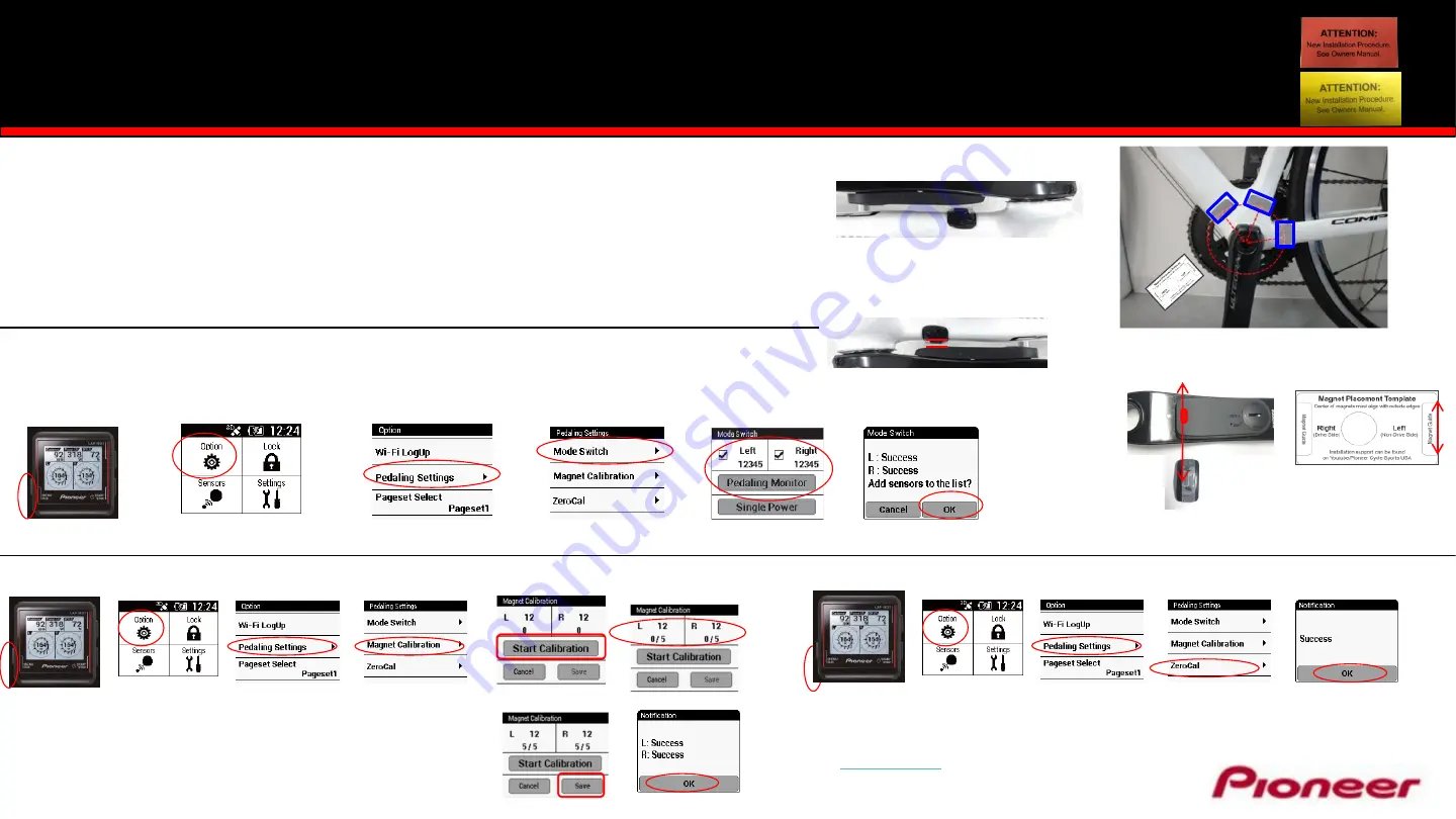
Magnet Placement
1. Measuring from the center of the bottom bracket out, temporarily tape the magnet so that the center line
of the magnet is:
•
Right Drive Side - 42mm
•
Left Side - 53mm
2. Use the supplied Magnet Placement Template to help locate the optimum locations for magnet placement
on the frame.
3. Position the magnets so the sensor line and magnet center line are parallel when the sensor passes over.
Center Magnet Placement Template hole on bottom bracket
and use supplied double sided tape to temporarily secure while
locating optimum magnet location.
Sensor Line:
Magnet
Center
Line:
Magnet Range
1.5mm
–
10.7mm
Magnet Template
card
Press Option
Press Pedaling Settings
Check Left & Right, Enter ANT+ ID,
Press Pedaling Monitor
Press Menu
•
Mode Selection & Pairing to the Pioneer Computer
1. Spin the crank 3
– 4 rotations to activate the Power Meter
2. Pressing
Pedaling Monitor
will search sensor ID or local crank.
SGX-CA500 firmware must be 20150501.02.43 or higher.
Press OK
ID 12345
Sensor
ID
Left Sensor Arm
•
Magnet Calibration
Press Option
Press Pedaling Settings
Press Menu
Press Magnet Calibration
Press Start calibration
Spin Crank Slowly Forward
Confirm 5 x per side
Press Save
1.
Spin the crank FORWARD slowly (30 rpm) until both left
and right sensors detect magnets at least 5 times for each
side and press Save.
Press OK
2. Secure magnets for final placement.
For additional Installation Instructions visit the following on-line support locations
www.pioneerelectronics.com/PUSA/Cycle+Sports/Products/Power+Meters
www.Youtube/Pioneer Cycle Sports USA
Please refer to the owners manual for detailed installation instructions.
Visit
for the latest firmware and updates.
Customer Support
– 1-800-421-1624
E-Mail: [email protected]
Press Option
Press Pedaling Settings
Press Magnet Calibration
Press Menu
Press OK
•
Zero Calibration
–
Position Left or Right crank arm to the 6 o’clock position
Easy Installation Power Meter Cranksets
with Pioneer Cycle Computer
Press Mode Switch


