En
7
English
POWER
Unbalanced
RCA
-10dB
-6dB
-4dB
+2dB
-2dB
0dB
0dB
Level
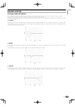
Low EQ
Mid EQ
High EQ
XLR
Auto Standby
AC IN
ON
OFF
ON
OFF
-4dB
0dB
-2dB
1dB
-4dB
+2dB
-2dB
0dB
5
4
6
b
8
9
a
7
2
3
1
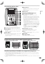
* The RM-05 is shown in the illustration.
1
Screw holes for the wall mount bracket
2
LOW EQ dial
Adjust the frequency response in the low frequency range.
See “Equalizer Settings” on page 9 for more details.
3
MID EQ dial
Adjust frequency attenuation in the approx. 100 Hz to 200 Hz
range.
See “Equalizer Settings” on page 9 for more details.
4
HIGH EQ dial
Adjust the frequency response in the high frequency range.
See “Equalizer Settings” on page 9 for more details.
5
LEVEL dial
Use to adjust the sound level (Volume).
6
RCA INPUT jack (Unbalanced)
7
AUTO STANDBY switch
Use to turn the auto standby function on or off.
When the auto standby function is turned on, the speakers
automatically enter standby mode if no input signal is received
for a certain period of time (approximately 25 minutes) and
power consumption can be reduced. When an input signal is
received while the speakers are in standby mode, the speakers
will automatically resume from standby mode.
• The illumination (POWER indicator) on the front panel turns
off when the speakers enter standby mode.
• When the input signal is weaker than a certain level, the
speakers may not automatically resume from standby
mode. In such cases, turn off the [
AUTO STANDBY
] switch
to use the speakers.
• To force the speakers to resume from standby mode, turn off
the [
POWER
] switch on the rear panel once, and turn it back
on after a few seconds.
8
XLR INPUT connector (Balanced)
The connector’s pin array is as follows:
No. 1 Ground, No. 2 Hot, and No. 3 Cold.
9
AC IN
Connect the accessory power cord here and to an AC power
outlet.
a
Fuse holder
b
POWER switch
Use to turn the power on and off.
Rear Panel Facilities
Cautions for Attaching to Wall Using a Mount Bracket
Use a mount bracket that is capable of supporting the weight of the unit. In regard to retail brackets, please direct any inquiries to
your retailer.
Perform an inspection of the wall etc. prior to performing the mounting, and ensure that it is strong enough to support the weight
of the unit.
Use screws that are suited to the materials of the wall to which the unit is being mounted.
After completing the mounting, be sure to perform a full safety check, and conduct periodic safety checks going forward.
Position of screw holes for the wall mount bracket
RM-05 (M6 10 mm deep 2 locations)
RM-07 (M6 10 mm deep 6 locations)
76.2 mm
108 mm
51 mm
70 mm
Summary of Contents for RM-05
Page 69: ...Ru 11 Русский ...


