


DEH-P40MP/XU/EW5
50
1
2
3
4
1
2
3
4
C
D
F
A
B
E
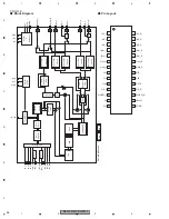
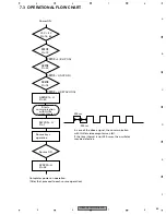
6.4 SYSTEM MICROCOMPUTER TEST PROGRAM
-
PCL Output
In the normal operation mode (with the detachable panel installed, the ACC switched ON, the standby mode
cancelled), shift the TESTIN IC601(Pin 88) terminal to H.
The clock signal is output from the PCL terminal IC601(Pin 39).
The frequency of the clock signal is 468 750 Hz that is one 32th of the fundamental frequency.
The clock signal should be 468 750 Hz(- 10 Hz, + 15 Hz).
If the clock signal is out of the range, the X'tal (X601) should be replaced with new one.
Summary of Contents for RDS DEH-P40MP
Page 6: ...DEH P40MP XU EW5 6 1 2 3 4 1 2 3 4 C D F A B E 1 SPECIFICATIONS ...
Page 7: ...DEH P40MP XU EW5 7 5 6 7 8 5 6 7 8 C D F A B E ...
Page 12: ...DEH P40MP XU EW5 12 1 2 3 4 1 2 3 4 C D F A B E 2 3 CD MECHANISM MODULE ...
Page 22: ...DEH P40MP XU EW5 22 1 2 3 4 1 2 3 4 C D F A B E 3 3 KEYBOARD UNIT B LCD DRIVER KEY CONTROLLER ...
Page 23: ...DEH P40MP XU EW5 23 5 6 7 8 5 6 7 8 C D F A B E B A CN804 B KEYBOARD UNIT ...
Page 27: ...DEH P40MP XU EW5 27 5 6 7 8 5 6 7 8 C D F A B E C a C b C b 2 3 A CN701 6 ...
Page 35: ...DEH P40MP XU EW5 35 5 6 7 8 5 6 7 8 C D F A B E A SIDE B PCL ...
Page 37: ...DEH P40MP XU EW5 37 5 6 7 8 5 6 7 8 C D F A B E ...
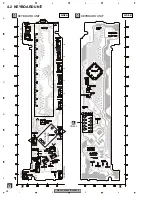
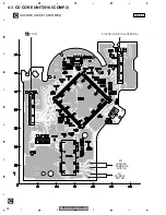
Page 39: ...DEH P40MP XU EW5 39 5 6 7 8 5 6 7 8 C D F A B E C SIDE B C CD CORE UNIT S10 5COMP2 ...
Page 64: ...DEH P40MP XU EW5 64 1 2 3 4 1 2 3 4 C D F A B E 7 2 2 DISPLAY LCD YAW5064 SEGMENT COMMON ...
Page 66: ...DEH P40MP XU EW5 66 1 2 3 4 1 2 3 4 C D F A B E 8 OPERATIONS ...
Page 67: ...DEH P40MP XU EW5 67 5 6 7 8 5 6 7 8 C D F A B E CBA1994 ...
Page 68: ...DEH P40MP XU EW5 68 1 2 3 4 1 2 3 4 C D F A B E Connection Diagram ...
Page 69: ...DEH P40MP XU EW5 69 5 6 7 8 5 6 7 8 C D F A B E ...