


DEH-P40MP/XU/EW5
2
1
2
3
4
1
2
3
4
C
D
F
A
B
E
SAFETY INFORMATION
CAUTION:
USE OF CONTROLS OR ADJUSTMENTS OR PERFORMANCE OF PROCEDURES OTHER THAN THOSE
SPECIFIED HEREIN MAY RESULT IN HAZARDOUS RADIATION EXPOSURE.
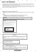
CLASS 1
LASER PRODUCT
WARNING!
The AEL (accessible emission level )of the laser power output is less than CLASS 1
but the laser component is capable of emitting radiation exceeding the limit for
CLASS 1.
A specially instructed person should do servicing operation of the apparatus.
Laser diode characteristics
Wave length : 785 nm to 814 nm
Maximum output : 1 190
μ
W(Emitting period : unlimited)
Additional Laser Caution
Transistors Q101 in PCB drive the laser diodes.
When Q101 is shorted between their terminals, the laser diodes will radiate beam.
If the top cover is removed with no disc loaded while such short-circuit is continued,
the naked eyes may be exposed to the laser beam.
-
Safety Precautions for those who Service this Unit.
• When checking or adjusting the emitting power of the laser diode exercise caution in order to get safe, reliable
results.
Caution:
1. During repair or tests, minimum distance of 13 cm from the focus lens must be kept.
2. During repair or tests, do not view laser beam for 10 seconds or longer.
This service manual is intended for qualified service technicians; it is not meant for the casual do-it-yourselfer.
Qualified technicians have the necessary test equipment and tools, and have been trained to properly and safely
repair complex products such as those covered by this manual.
Improperly performed repairs can adversely affect the safety and reliability of the product and may void the warranty.
If you are not qualified to perform the repair of this product properly and safely, you should not risk trying to do so
and refer the repair to a qualified service technician.
Summary of Contents for RDS DEH-P40MP
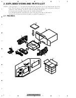
Page 6: ...DEH P40MP XU EW5 6 1 2 3 4 1 2 3 4 C D F A B E 1 SPECIFICATIONS ...
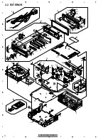
Page 7: ...DEH P40MP XU EW5 7 5 6 7 8 5 6 7 8 C D F A B E ...
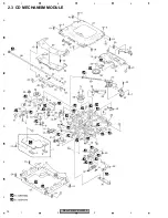
Page 12: ...DEH P40MP XU EW5 12 1 2 3 4 1 2 3 4 C D F A B E 2 3 CD MECHANISM MODULE ...
Page 22: ...DEH P40MP XU EW5 22 1 2 3 4 1 2 3 4 C D F A B E 3 3 KEYBOARD UNIT B LCD DRIVER KEY CONTROLLER ...
Page 23: ...DEH P40MP XU EW5 23 5 6 7 8 5 6 7 8 C D F A B E B A CN804 B KEYBOARD UNIT ...
Page 27: ...DEH P40MP XU EW5 27 5 6 7 8 5 6 7 8 C D F A B E C a C b C b 2 3 A CN701 6 ...
Page 35: ...DEH P40MP XU EW5 35 5 6 7 8 5 6 7 8 C D F A B E A SIDE B PCL ...
Page 37: ...DEH P40MP XU EW5 37 5 6 7 8 5 6 7 8 C D F A B E ...
Page 39: ...DEH P40MP XU EW5 39 5 6 7 8 5 6 7 8 C D F A B E C SIDE B C CD CORE UNIT S10 5COMP2 ...
Page 64: ...DEH P40MP XU EW5 64 1 2 3 4 1 2 3 4 C D F A B E 7 2 2 DISPLAY LCD YAW5064 SEGMENT COMMON ...
Page 66: ...DEH P40MP XU EW5 66 1 2 3 4 1 2 3 4 C D F A B E 8 OPERATIONS ...
Page 67: ...DEH P40MP XU EW5 67 5 6 7 8 5 6 7 8 C D F A B E CBA1994 ...
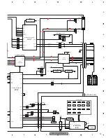
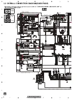
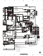
Page 68: ...DEH P40MP XU EW5 68 1 2 3 4 1 2 3 4 C D F A B E Connection Diagram ...
Page 69: ...DEH P40MP XU EW5 69 5 6 7 8 5 6 7 8 C D F A B E ...