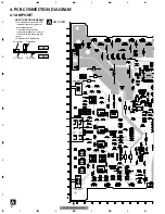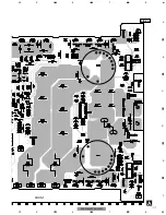
4. PCB CONNECTION DIAGRAM
4.1 AMP UNIT
Capacitor
Connector
P.C.Board
Chip Part
A
A
AMP UNIT
SIDE B
SIDE A
NOTE FOR PCB DIAGRAMS
1.The parts mounted on this PCB
include all necessary parts for
several destination.
For further information for
respective destinations, be sure
to check with the schematic dia-
gram.
2.Viewpoint of PCB diagrams
1
2
3
4
5
6
9
10
11
12
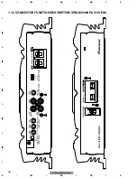
Lch
Rch
SYNC
INPUT
SYNC
OUTPUT
SUB SONIC
FILTER SWITCH
MODE SELECT
SWITCH
16
1
2
3
4
1
2
3
4
F
E
D
C
B
A
PRS-D3000SPL/X1H/EW
Summary of Contents for PRS-D3000SPL/X1H/EW
Page 12: ...12 1 2 3 4 1 2 3 4 F E D C B A PRS D3000SPL X1H EW A a A b A a A a A b 1 2 3 4 5 ...
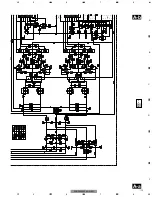
Page 13: ...13 5 6 7 8 F E D C B A 5 6 7 8 PRS D3000SPL X1H EW A a A b A a A a A b 6 7 8 ...
Page 14: ...14 1 2 3 4 1 2 3 4 F E D C B A PRS D3000SPL X1H EW A a A b A b 1 2 3 4 5 A AMP UNIT ...
Page 17: ...17 5 6 7 8 F E D C B A 5 6 7 8 PRS D3000SPL X1H EW A SIDE A BFC SWITCH FRONT ...
Page 18: ...18 1 2 3 4 1 2 3 4 F E D C B A PRS D3000SPL X1H EW A A AMP UNIT ...
Page 19: ...19 5 6 7 8 F E D C B A 5 6 7 8 PRS D3000SPL X1H EW A SIDE B 1 ...


