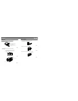

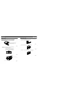

Fixing the Front Panel
If you do not operate the Detaching and Replacing the Front Panel Function, use the sup-
plied fixing screws and holder to fix the front panel to this unit.
1. Attach the holder to the front panel. (Fig. 11)
Fig. 11
2. Replace the front panel to the unit. (Fig. 12)
Fig. 12
3. Fix the front panel to the unit using fixing screws. (Fig. 13)
Fig. 13
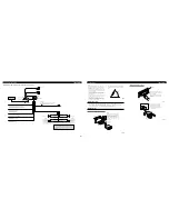
DIN Rear-mount
Installation using the screw holes on the side of the unit
1. Remove the frame. (Fig. 8)
Fig. 8
2. Fastening the unit to the factory radio mounting bracket.
(Fig. 9) (Fig. 10)
Select a position where the screw holes of the bracket and
the screw holes of the head unit become aligned (are fitted),
and tighten the screws at 2 places on each side. Use either
truss screws (5
×
8 mm) or flush surface screws
(5
×
9 mm), depending on the shape of the screw holes in
the bracket
.
Fig. 9
Fig. 10
Frame
Insert the release pin into the hole in
the bottom of the frame and pull out
to remove the frame.
(When reattaching the frame, point
the side with a groove downwards
and attach it.)
Screw
Dashboard or Console
Factory radio mounting bracket
Fixing screw
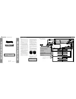
Installation
<ENGLISH>
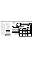
Installation
<ENGLISH>


