PDR-W739
3
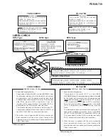
KUXJ/CA Type
Printed on Rear Panel
Printed on Rear Panel
NYXJ and NVXJ Types
NYXJ Type
NVXJ Type
NYXJ Type
USYNLIG LASERSTRÅLING VED ÅBNING NÅR SIKKERHED SAF-
BRYDERE ER UDE AF FUNKTION.
UNDGÅ UDSÆTTELSE FOR STRÅLING
UNSICHTBARE LASER-STRAHLUNG TRITT AUS, WENN DECKEL
(ODER KLAPPE) GEÖFFNET IST! NICHT DEM STRAHL AUSSETZEN!
VRW1094
ADVARSEL
VORSICHT!
IMPORTANT
T H I S P I O N E E R A P P A R A T U S C O N T A I N S
LASER OF CLASS
ΙΙΙ
b.
SERVICING OPERATION OF THE APPARATUS
S H O U L D B E D O N E B Y A S P E C I A L L Y
INSTRUTED PERSON.
LASER DIODE CHARACTERISTICS
MAXIMUM OUTPUT POWER: 23 mW
WAVELENGTH: 778 – 787 nm
1. Laser Interlock Mechanism
The position of the switch (S501) on the LOADING A Assy
for detecting loading state is detected by the system
microprocessor, and the design prevents laser diode
oscillation when the switch (S501) is not on TRAY terminal
side (TRAY signal is OFF or high level.). Thus, the
interlock will no longer function if the switch (S501) is
deliberately set to TRAY terminal side (low level).
The interlock also does not function in the test mode
∗
.
Laser diode oscillation will continue, if pin 32 of CN101 on
the CD-R CORE ASSY is connected to low level.
2. When the cover is opened with the servo mechanism
block removed and turned over, close viewing of the
objective lens with the naked eye will cause exposure to a
Class 1 laser beam.
Additional Laser Caution
∗
Refer to page 64.
LABEL CHECK
CD RECORDER
CD PLAYER
IMPORTANT
T H I S P I O N E E R A P P A R A T U S C O N T A I N S
LASER OF CLASS 1.
SERVICING OPERATION OF THE APPARATUS
S H O U L D B E D O N E B Y A S P E C I A L L Y
INSTRUCTED PERSON.
LASER DIODE CHARACTERISTICS
MAXIMUM OUTPUT POWER: 5 mW
WAVELENGTH: 760 - 800 nm
1. Laser Interlock Mechanism
The position of the switch (S101) on the SERVO
MECHANISM Assy for detecting loading state is detected
by the system microprocessor, and the design prevents
laser diode oscillation when the switch (S101) is not on
CLMP terminal side (CLMP signal is OFF or high level.).
Thus, the interlock will no longer function if the switch
(S101) is deliberately set to CLMP terminal side (low
level).
The interlock also does not function in the test mode
∗
.
Laser diode oscillation will continue, if pin 1 of CXA2570
(IC1101) on the MAIN ASSY is connected to GND, or pin
12 is connected to low level (ON), or else the terminals of
Q1101 are shorted to each other (fault condition).
2. When the cover is opened with the servo mechanism
block removed and turned over, close viewing of the
objective lens with the naked eye will cause exposure to a
Class 1 laser beam.
Additional Laser Caution
∗
Refer to page 63.
CD RECORDER
CD PLAYER
Summary of Contents for PDR-W739
Page 20: ...PDR W739 20 A B C D 1 2 3 4 1 2 3 4 A2 5 A1 5 A5 5 A2 5 2 3 5 CD R CORE ASSY 3 5 3 5 A ...
Page 48: ...PDR W739 48 A B C D 1 2 3 4 1 2 3 4 H IC1505 IC1503 Q1501 IC1504 IC1502 MAIN ASSY H ...
Page 49: ...PDR W739 49 A B C D 5 6 7 8 5 6 7 8 H PNP1472 A SIDE B ...
Page 55: ...PDR W739 55 A B C D 5 6 7 8 5 6 7 8 N L HEAD PHONE ASSY L OPERATING1 ASSY N CN802 H CN1402 H ...
Page 56: ...PDR W739 56 A B C D 1 2 3 4 1 2 3 4 N L HEAD PHONE ASSY L OPERATING1 ASSY N Q708 IC701 ...
Page 86: ...86 PDR W739 ...

