PDP-R04E
101
5
6
7
8
5
6
7
8
C
D
F
A
B
E
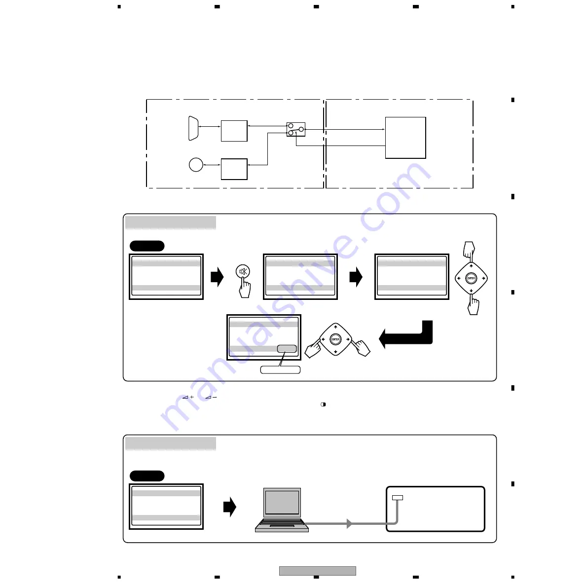
6.3 USING RS-232C COMMANDS
Rough diagram of switching between SR+ and RS-232C
How to switch from SR+ to RS-232C
For the PDP-434HD and -504HD series Plasma Displays, the circuitry is structured as shown in the diagram below to support
the SR+ system. Controlling with either the SR+ system or RS-232C commands can be selected. As the SR+ system is
selected at shipment, to control with RS-232C commands in servicing it is necessary to switch the paths. After servicing, be
sure to return the setting to the SR+ system.
232C (DSUB_9P)
TXD (EXT), RXD (EXT)
SR_EN_B
SR+ (SR out)
232C
Driver
IC9702
(IF Microcomputer)
SR+
Interface
SR Assy
AV BOARD Assy
Remote control unit
Media Receiver
PC
RS-232C
START
INFORMATION
VERSION
INITIALIZE
SYNC DET
MUTE
Up
Down
Select
INITIALIZE
mode
INITIALIZE
UART SELCT
Select
UART
Enter the Service Factory mode
SR+
→
232C / 232C
→
SR+
Send the command "BR0"
Command "BR0"
Left
Right
INITIALIZE
UART
Select
SR+ / 232C
SR+
↔
232C
PC
START
INFORMATION
VERSION
Enter the Service Factory mode
(See "6.7 SERVICE FACTORY MODE".)
232C
→
SR+ only
Tips: How to change the SR+/RS-232C setting without entering Service Factory mode
Hold the
VOLUME
or key on the remote control unit pressed for 3-10 seconds during Standby mode.
Then within 3 seconds after the key is released, hold the
2-screen
key on the remote control unit pressed for 3-10 seconds.
Then within 3 seconds after the key is released, use the
SET
key on the remote control unit to set to RS-232C (the baud rate
last selected is chosen) or the
HOME MENU
key to set to SR+.
Summary of Contents for PDP-R04E
Page 27: ...27 5 6 7 8 5 6 7 8 C D F A B E PDP R04G B 6 8F 5 8F B 5 8F B 5 8F B 5 8F B ...
Page 29: ...29 5 6 7 8 5 6 7 8 C D F A B E PDP R04G B 7 8F 8 8F B ...
Page 31: ...31 5 6 7 8 5 6 7 8 C D F A B E PDP R04G B 8 8F ...
Page 33: ...33 5 6 7 8 5 6 7 8 C D F A B E PDP R04G CN8501 CP51 G I F ...
Page 37: ...37 5 6 7 8 5 6 7 8 C D F A B E PDP R04G SIDE B ANP2044 B AV BOARD ASSY B F B F ...
Page 92: ...PDP R04E 41 5 6 7 8 5 6 7 8 C D F A B E ...
Page 96: ...PDP R04E 45 5 6 7 8 5 6 7 8 C D F A B E A 12 13 1 13 9 13 11 13 13 13 A 9 13 A 9 13 A ...
Page 100: ...PDP R04E 49 5 6 7 8 5 6 7 8 C D F A B E B 1 8 1 2 5 8 B 2 8 B 3 8 B 5 8 B 2 8 3 8 B ...
Page 110: ...PDP R04E 59 5 6 7 8 5 6 7 8 C D F A B E B 6 8 5 8 B ...
Page 112: ...PDP R04E 61 5 6 7 8 5 6 7 8 C D F A B E B 7 8 8 8 B ...
Page 114: ...PDP R04E 63 5 6 7 8 5 6 7 8 C D F A B E B 8 8 ...
Page 115: ...PDP R04E 64 1 2 3 4 1 2 3 4 C D F A B E 3 24 MDR ASSY C MDR ASSY AWZ6778 C ...
Page 116: ...PDP R04E 65 5 6 7 8 5 6 7 8 C D F A B E C CN7402 A 12 13 ...
Page 117: ...PDP R04E 66 1 2 3 4 1 2 3 4 C D F A B E 3 25 SR ASSY D SR ASSY AWZ6817 D ...
Page 118: ...PDP R04E 67 5 6 7 8 5 6 7 8 C D F A B E D CN8658 B 5 8 ...
Page 119: ...PDP R04E 68 1 2 3 4 1 2 3 4 C D F A B E 3 26 FRONT ASSY 1 2 E 1 2 ...
Page 122: ...PDP R04E 71 5 6 7 8 5 6 7 8 C D F A B E 3 28 LED ASSY LED ASSY AWZ6816 F F CN8656 B 5 8 ...
Page 124: ...PDP R04E 73 5 6 7 8 5 6 7 8 C D F A B E G CN8504 PC CARD MODULE B 4 8 CN8503 B 4 8 ...
Page 126: ...PDP R04E 75 5 6 7 8 5 6 7 8 C D F A B E I CN8501 G ...
Page 140: ...PDP R04E 89 5 6 7 8 5 6 7 8 C D F A B E SIDE B B AV BOARD ASSY B ANP2043 E ...
Page 190: ...PDP R04E 139 5 6 7 8 5 6 7 8 C D F A B E 49 TP7710 ...
Page 224: ...PDP R04E 173 5 6 7 8 5 6 7 8 C D F A B E Schematic Diagram ...


