background image

16

Fr

Installation et raccordements

Fran

ç

ais

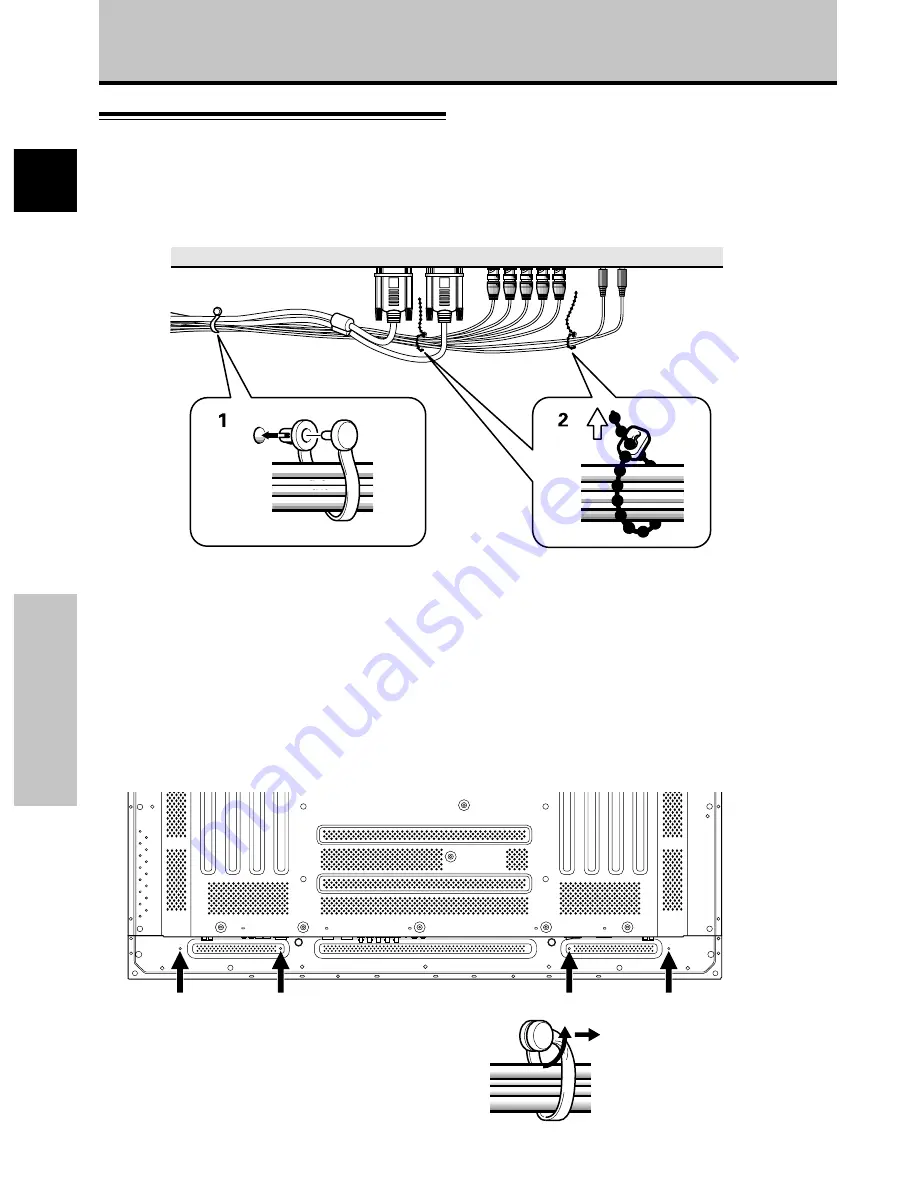
Comment faire cheminer les câbles

Des colliers rapides et des serre-câble sont fournis pour
lier les câbles en tre eux. Après raccordements des
appareils, procédez aux opérations qui suivent.

1

Groupez les câbles en utilisant les colliers rapides
fournis.

Introduisez la partie 

1

 dans un des perçages à

l’arrière de l’écran à plas ma puis insérez 

2

 à l’arrière

de 

1

  pour assurer la fixation.

Les colliers rapides sont conçus pour que l’ouverture
soit difficile. Fermez-les soigneusement.

Fixation des colliers rapides à l’écran à plasma

Engagez les colliers rapides dans les trous 4 repérés
par • sur l’illustration ci-dessous.

Pour retirer les colliers rapides

A l’aide d’une pince, tordez le collier de 90° puis tirez-le
vers vous. Avec le temps, le collier peut se détériorer et il
peut être nécessaire de la remplacer après que vous
l’avez retiré.

* Vue de l’arrière de l’écran.

Installation et raccordements

1

2

2

Liez les câbles et assurez leur maintien au moyen
des serre-câble fournis.

Remarque

Les câbles peuvent cheminer d’un côté ou de l’autre.

Cette illustration présente le modèle PDP-503MXE.

Summary of Contents for PDP-503MXE

Page 1: ...PDP 503MXE PDP 433MXE Plasma Display Écran à plasma Plasma Display Operating Instructions Mode d emploi Bedienungsanleitung ...

Page 2: ...ilisation comme moniteur d affichage d ordinateur La carte vidéo optionnelle est nécessaire si vous souhaitez regarder d autres signaux sur ce moniteur Pour plus de renseignements consultez votre revendeur Deutsch Dieses Gerät ist als Monitor für Personalcomputer konzipiert Wenn andere Videosignale auf diesem Monitor betrachtet werden sollen muss die optionale Videokarte installiert werden Weitere...

Page 3: ...u will find it useful in the future Notes on Installation Work This product is marketed assuming that it is installed by qualified personnel with enough skill and competence Always have an installation specialist or your dealer install and set up the product PIONEER cannot assume liabilities for damage caused by mistake in installation or mounting misuse modification or a natural disaster Note for...

Page 4: ... cause heat to build up inside resulting in fire hazards Do not attempt to fit the unit inside narrow spaces where ventilation is poor Do not place on carpet Do not cover with cloth etc Do not place on its side Do not place it upside down If planning special installation such as fitting close to the wall placing it horizontally etc be sure to consult your Pioneer dealer first WARNING THIS APPARATU...

Page 5: ... Setting Up the System 17 Setup after Connection 17 Operations 19 Selecting an Input Source 19 Screen Size Selection 21 Partial Image Enlargement POINT ZOOM 23 Automatic Power OFF 24 Display Panel Adjustments 25 Adjusting the Picture Quality 25 Adjusting the Image Position and Clock Automatic Adjustment 26 Manual Adjustment of Screen Position and Clock 27 Other Operations 28 Rewriting the Input Di...

Page 6: ...n adjustment AUTO SETUP function for computer connections and the POINT ZOOM function to enlarge local portions of the screen image to display important detailed program data Power Saving Design While equipped with a high precision 1280x768 panel this unit achieves the highest energy saving of any display in its class 50 inch XGA class 380 W 20 less than previous Pioneer products In addition when ...

Page 7: ...this section may or may not be necessary The remainder of the sections in this manual is dedicated to the basic operations associated with selecting a source component up to the more complex operations associated with adjusting the plasma display picture to match the requirements of specific components and personal preferences Screen Displays The example screen displays provided in this manual are...

Page 8: ...ontinuing on with the rest of this manual 1 Press MENU to display the menu screen MAIN MENU INPUT1 SELECT ENTER EXIT SET MENU PICTURE SCREEN SET UP OPTION 0 6 0 6 0 6 0 0 0 CONT RAST 0 BR R L EV EL I GHT G L EV EL B L EV EL H E NHANCE V E NHANCE R S ET E 2 Press 3 to select SCREEN SELECT ENTER EXIT SET MENU PICTURE SCREEN SET UP OPTION 0 0 POS I T I ON CL OC HAS E K 0 0 P R S ET E MAIN MENU INPUT1...

Page 9: ... x 2 3 Cleaning cloth for wiping front panel 4 Speed clamps x 2 5 Bead bands x 2 6 Ferrite core Before Proceeding 7 Display stands x 2 8 Washers x 2 9 Hex hole bolts x 2 0 Remote control unit holder Cable tie Operating Instructions Use as a holder for the remote control unit When attaching to the rear of the main unit be careful not to cover the vents ...

Page 10: ... mode page 19 5 INPUT button Press to select input page 19 6 MENU button Press to open and close the on screen menu pages 17 to 30 7 ADJUST 5 3 2 buttons Use to navigate menu screens and to adjust various settings on the unit Usage of cursor buttons within operations is clearly indicated in the on screen display pages 17 to 30 8 SET button Press to adjust or enter various settings on the unit page...

Page 11: ...size page 21 2 INPUT buttons Use to select the input page 19 3 MENU button Press to open and close the on screen menu pages 17 to 30 4 ADJUST 5 3 2 buttons Use to navigate menu screens and to adjust various settings on the unit Usage of cursor buttons within operations is clearly indicated at the bottom the on screen menu display pages 17 to 30 5 SET button Press to adjust or enter various setting...

Page 12: ...rom the OUTPUT INPUT1 terminal when the main power of this unit is off or in standby mode page 13 7 INPUT2 BNC jacks For connection of a personal computer PC or similar component Make sure that the connection made corresponds to the format of the signal output from the connected component pages 12 to 14 If you are having difficulty with operation of the remote control unit The remote control unit ...

Page 13: ...e component s synchronization signal is below 75 Ω set this switch to the 75 Ω position pages 12 14 9 AUDIO INPUT Stereo mini jack Use to obtain sound when INPUT1 or INPUT2 is selected Connect the audio output jack of components connected to INPUT1 or INPUT2 to this unit page 14 0 AUDIO OUTPUT Stereo mini jack Use to output the audio of the selected source component connected to this unit to an AV...

Page 14: ... Fix the supplied stand to the installation surface at each of the 4 prepared holes using commercially available M8 bolts 2 Set this unit in the stand Front Rear PDP 503MXE 798 mm PDP 433MXE 768 mm 110 mm Use a 6 mm hex wrench to bolt them CAUTION This display unit weighs at least 30 kg and has little front to back depth making it very unstable when stood on edge As a result two or more persons sh...

Page 15: ...Use bolts that are long enough to be inserted 12 mm to 18 mm into the main unit from the attaching surface for both a holes and b holes Refer to the side view diagram below As this unit is constructed with glass be sure to install it on a flat unwarped surface CAUTION Please be sure to use an M8 Pitch 1 25 mm bolt Only this size bolt can be used CAUTION This display unit weighs at least 30 kg and ...

Page 16: ...s jack Connection to a personal computer Connection method differs depending on the computer type When connecting please thoroughly read the computer s instruction manual Before making connections be sure to make sure that the personal computer s power and this unit s main power is off For the PC input signals and screen sizes that this unit is compatible with please refer to supplement 1 pages 35...

Page 17: ...G RGB INPUT1 OUTPUT With this unit it is possible to output the video signal to an external monitor or other component from the OUTPUT INPUT1 terminal Note A video signal will not be output from the OUTPUT INPUT1 terminal when the main power of this unit is off or in standby To an external monitor Connection of SYNC ON G analog RGB source Make SYNC ON G connections for a personal computer with out...

Page 18: ...nt s power and the unit s main power is off Connecting the speakers This unit is equipped with speaker output terminals for connection to the speaker system not supplied specially designed for use with this unit Refer to the illustrations below when making connections to the speaker terminals on this unit 10 mm Note When making speaker connections be sure to match the polarities and of the speaker...

Page 19: ... completed PDP 503MXE PDP 433MXE power cord ratings Cord Cross sectional area 3 x 1 0 mm2 According to CEE 13 Connector 10 A 250 V According to EN60320 Sheet C13 Plug International use 10 A 250 V Example UK UK 13 Amp Plug with rated 13 Amp fuse According to BS1363 EURO 10 A 16 A 250 V According to CEE 7 1 V CAUTION Do not use a power supply voltage other than that indicated AC 100 240 V 50 60 Hz a...

Page 20: ...gned to be difficult to undo once in place Please attach carefully To attach the speed clamps to the main unit Connect the speed clamps using the 4 holes marked with Black dot below depending on the situation As viewed from the rear of the display Installation and Connections 1 2 To remove speed clamps Using pliers twist the clamp 90 and pull it outward In some cases the clamp may have deteriorate...

Page 21: ...N SYNC or Composite SYNC signal for WIDE VGA or WIDE XGA inputs set the screen display mode manually 8 When the setup is completed press MENU to exit the menu screen Note Make this setup for each input INPUT1 and INPUT2 Setup after Connection After components have been connected to INPUT1 or INPUT2 on screen setup is necessary Follow the procedure described below and make settings as they apply to...

Page 22: ... A I NP UT I NP UT 1 L E B L A MAIN MENU INPUT1 3 Press 5 to select CLAMP POSITION SELECT CHANGE EXIT SET MENU PICTURE SCREEN SET UP OPTION NT S E T T I N CL AMP POWE R G OF F P S I T I ON O M NAGEME A I NP UT I NP UT 1 L E B L A V GA A U TO MAIN MENU INPUT1 4 Press SET to select LOCKED SELECT CHANGE EXIT SET MENU PICTURE SCREEN SET UP OPTION NT S E T T I N CL AMP POWE R G OF F P S I T I ON O M NA...

Page 23: ...gnal input will cause the menu screen to turn off If the input computer signal is not supported by the display the following message will be displayed 0 8 5 5 1 2 6 8 4 k H z f V 1 7 1 7 H z f H P O U SUP N S R ED T I NAL G CAU I O N T FUL L I NPUT 1 X 0 2 0 k H z f V 7 7 1 5 H z f H T OU N O A R F G E CAU I O N T FUL L I NPUT 1 4 Use VOLUME on the remote control unit to adjust the volume If no au...

Page 24: ...tomatically canceled about 8 minutes after the button is pressed and the volume level is adjusted to the minimum level Press VOLUME or VOLUME to adjust the volume at a desired level To confirm display settings DISPLAY Press DISPLAY on the remote control unit The currently selected input screen size and refresh rates will be displayed for about 3 seconds O D BY T DOT I NPUT 1 0 6 0 4 6 0 8 4 0 k H ...

Page 25: ...n a wide screen a portion of the picture may be cut off or appear deformed Be aware that when the display is used for commercial or public viewing purposes selecting the PARTIAL or FULL mode settings may violate the rights of authors protected under copyright law When DOT BY DOT or 4 3 screen sizes are selected the display position is moved slightly each time the power is turned on in order to pre...

Page 26: ... source However in order to maintain the 1 1 ratio a portion of the display will not appear on the screen Use 5 to adjust the position of the video image on the screen 768 lines 1024 lines Moving the screen position upward or downward Supported only on PDP 503MXE During personal computer input 1280 x 1024 60Hz only even when the PARTIAL setting is selected the position of the screen can be adjuste...

Page 27: ... used to move the enlarged portion up down and right left If no operation is undertaken for three seconds or more the display screen will disappear SET or 5 2 3 can be pressed again if desired to change the zoom ratio or display position 4 Press the remote control unit s POINT ZOOM once again to cancel the point zoom operation The point zoom function will also be canceled whenever the input signal...

Page 28: ...S E T T I N CL AMP POWE R G OF F P S I T I ON O M NA GEME A I NP UT I NP UT 1 L E B L A V GA NT MAIN MENU INPUT1 When using INPUT 2 PICTURE SCREEN SET UP OPTION V GA AU T O S E T T I N CL AMP A UTO POWE R G OF F OF F P S I T I ON O I NP UT I NP UT 2 L E B L A MAIN MENU INPUT2 4 Press SET to confirm selection of the POWER MANAGEMENT or AUTO POWER OFF When OFF is selected the display will continue i...

Page 29: ...s PICTURE mode adjustment items Below are brief descriptions of the options that can be set in the PICTURE mode CONTRAST Adjust according to the surrounding brightness so that the picture can be seen clearly BRIGHT Adjust so that the dark parts of the picture can be seen clearly R LEVEL Adjust the amount of red in the picture G LEVEL Adjust the amount of green in the picture B LEVEL Adjust the amo...

Page 30: ...ote Perform this adjustment individually for each input function INPUT 1 INPUT 2 and each signal type Press AUTO SET UP on either the main unit or remote control unit Optimum settings may not be possible for low luminance and certain other kinds of signals In this case follow the instructions in the section Manual Adjustment of Screen Position and Clock to make more precise adjustments AUTO SET UP...

Page 31: ...ow are brief descriptions of the options that can be set in the SCREEN mode POSITION H POSITION Adjust the picture s position to the left or right V POSITION Adjust the picture s position upward or downward CLOCK PHASE CLOCK Adjust letter breakup or noise on the screen This setting adjusts the unit s internal clock signal frequency that corresponds to the input video signal PHASE Adjust so that th...

Page 32: ...E B L A T E S RE D N E A E C A S P MAIN MENU INPUT1 5 Press 2 3 5 to select the first desired character here C then press SET to confirm repeat this step to input up to eight desired characters SELECT SET EXIT SET MENU BACK SPACE J M K L B C D E F G H W Z X Y N O P Q R S T V U 9 0 1 2 3 4 5 6 8 7 I NP UT I NP UT 1 L E B L A T E S RE E C A S P D N E A C I MAIN MENU INPUT1 Usable characters include ...

Page 33: ... setting but at a even lower levels of power consumption MODE 2 fixes the screen brightness regardless of the input signal This is effective for reducing panel deterioration due to screen burning 4 Following completion of settings press MENU to return to normal screen display Note The POWER CONTROL setting affects all input sources AUTO FUNCTION This display is equipped with an optional AUTO FUNCT...

Page 34: ...DIO OUT The signal level produced at the AUDIO OUT jack can be set to FIXED or VARIABLE linked to the VOLUME as desired 1 Press MENU The onscreen menu will be displayed MAIN MENU INPUT1 SELECT ENTER EXIT SET MENU PICTURE SCREEN SET UP OPTION 0 6 0 6 0 6 0 0 0 CONT RAST 0 BR R L EV EL I GHT G L EV EL B L EV EL H E NHANCE V E NHANCE R S ET E 2 Press 2 3 to select OPTION SELECT CHANGE EXIT SET MENU P...

Page 35: ...ooting What may at first seem to be an malfunction may be remedied with a quick check Please check to see if a warning is displayed on the screen If displayed refer to the table below and check the mode If there is no display check to see if the problem is listed on page 32 The problem may also be caused by something other than this unit so please also check the other components being used such as...

Page 36: ...n is displayed in a small size Letter breakup on screen A sharp sound is sometimes heard from the cabinet Bright portions of image appear to be losing intensity Speckles or noise appears on screen Stripes appear on the screen Operation is not possible Sound is heard from inside the unit Fan isn t moving Fan speed changes Check the input signal compatibility chart pages 35 and 36 Is the correct scr...

Page 37: ...he problem persists disconnect the power plug and consult your dealer or a service center When STANDBY ON is pressed to set the unit to the standby mode the indicator will flash red for several seconds page 19 Other than this if the power turns off by itself or refuses to turn on or if the red indicator conditions flashing a malfunction may be indicated Immediately disconnect the power plug and co...

Page 38: ...ini D sub 15 pin socket connector RGB signal SYNC ON G compatible RGB 0 7 Vp p 75 Ω no sync HD CS VD TTL level positive and negative polarity 2 2 kΩ SYNC ON G 1 Vp p 75 Ω negative sync Compatible with Microsoft s Plug Play VESA DDC1 2B Output Mini D sub 15 pin socket connector 75 Ω with buffer Additional Information INPUT 2 Input BNC jack x5 RGB signal SYNC ON G compatible RGB 0 7 Vp p 75 Ω no syn...

Page 39: ... 9kHz 53 7kHz 49 7kHz 31 7kHz 48 4kHz 56 5kHz 60 0kHz 60 2kHz 68 7kHz 53 7kHz 64 9kHz 67 7kHz 68 7kHz 61 8kHz 71 7kHz 45 1kHz 48 4kHz 56 1kHz 60 0kHz 64 0kHz 80 0kHz 91 1kHz 75 0kHz 81 3kHz 87 5kHz 93 8kHz 106 3kHz 1024x768 1024x768 1024x768 1024x768 1016x768 984x768 1024x768 960x768 1024x768 640x480 800x600 832x624 852x480 1024x768 1280x768 4 3 NEC PC 9800 NEC PC 9800 852x480 864x480 Apple Macint...

Page 40: ...3 7kHz 64 9kHz 67 7kHz 68 7kHz 61 8kHz 71 7kHz 45 1kHz 48 4kHz 56 1kHz 60 0kHz 64 0kHz 80 0kHz 91 1kHz 75 0kHz 81 3kHz 87 5kHz 93 8kHz 106 3kHz 768x768 768x768 768x768 768x768 768x768 768x768 738x768 768x768 720x768 768x768 640x480 800x600 832x624 852x480 1024x768 4 3 NEC PC 9800 NEC PC 9800 852x480 864x480 Apple Macintosh 13 1072x600 Apple Macintosh 16 1376x768 indicates Apple Macintosh 19 Apple ...

Page 41: ...ine resolution Supplement 2 Signal assignment of INPUT 1 Mini D sub 15 pin socket connector Input Output 1 2 3 4 5 6 7 8 9 10 11 12 13 14 15 R or CR PR G or Y B or CB PB NC No connection GND GND GND GND DDC 5V GND NC No connection DDC SDA HD or H V SYNC VD DDC SCL NC No connection NC No connection NC No connection Pin No Apple and Macintosh are registered trademarks of Apple Computer Inc Microsoft...

Page 42: ...38 En Published by Pioneer Corporation Copyright 2002 Pioneer Corporation All rights reserved ...

Page 43: ...le dans les mois ou les années qui suivent Remarques sur l installation Ce produit est vendu en assumant qu il sera installé par un personnel suffisamment expérimenté et qualifié Faites toujours réaliser le montage et l installation par un spécialiste ou par votre revendeur PIONEER ne peut être tenu responsable pour tout dommage causé par une erreur d installation ou de montage une mauvaise utilis...

Page 44: ... qui entraînent l obstruction des orifices et provoquent une accumulation de chaleur interne d où un risque d incendie Ne pas essayer de placer l unité dans des espaces réduirts et mal ventilés Ne pas la placer sur un tapis Ne pas la recouvrir d un tissu etc Ne pas la placer sur le côté Ne pas la renverser Si une installation spéciale est envisagée comme un montage à proximité immédiate du mur un ...

Page 45: ...6 Mise en œuvre de l ensemble 17 Mise en œuvre après raccordement 17 Fonctionnement 19 Choix de la source 19 Choix du format de l image 21 Agrandissement partiel de l image POINT ZOOM 23 Mise hors tension automatique 24 Réglages de l écran à plasma 25 Réglage de la qualité de l image 25 Réglage automatique de la position de l image et de l horloge 26 Réglage manuel de la position d écran et de l h...

Page 46: ...nsion murale Applique d installation murale conçue comme support de fixation de l appareil 3 Enceintes acoustiques spécialement conçues pour les écrans à plasma largeur 7 4 cm Adoption d un système vertical à 2 voies composé d un haut parleur d aigus conique à dôme de 2 5 cm et de nouveaux haut parleurs de forme ovale d une largeur de 4 5 cm disposés verticalement Lorsque les hauts parleurs sont f...

Page 47: ...tres appareils de l installation En fonction des raccordements réalisés il peut être inutile de lire cette section Les autres sections de ce mode d emploi abordent des opérations de base telle le choix d une source et des opérations plus détaillées telles que l affichage d image correspondant aux appareils utilisés et aux goûts personnels Affichages d écran Les affichages d écran présentés à titre...

Page 48: ...pour afficher la page de menu MAIN MENU INPUT1 SELECT ENTER EXIT SET MENU PICTURE SCREEN SET UP OPTION 0 6 0 6 0 6 0 0 0 CONT RAST 0 BR R L EV EL I GHT G L EV EL B L EV EL H E NHANCE V E NHANCE R S ET E 2 Utilisez les touches 3 pour choisir l option SCREEN SELECT ENTER EXIT SET MENU PICTURE SCREEN SET UP OPTION 0 0 POS I T I ON CL OC HAS E K 0 0 P R S ET E MAIN MENU INPUT1 Remarque Les affichages ...

Page 49: ...iffon de nettoyage pour essuyer l écran 4 2 colliers rapides 5 2 serre câble 6 Noyau en ferrite Avant de commencer 7 2 supports pour l écran 8 2 rondelles petite 9 2 boulons hexagonaux 0 Support pour télécommande Attache de câble Mode d emploi Utilisez ce support pour y ranger la télécommande Si vous fixez ce support à l arrière de l écran veiller à ne pas obstruer les ouïes d aération ...

Page 50: ...sur cette touche pour choisir le signal d entrée page 19 6 Touche MENU Appuyez sur cette touche pour ouvrir ou fermer les menus s affichant sur l écran pages 17 à 30 7 Touche ADJUST 5 3 2 Utilisez ces touches pour naviguer dans les menus et choisir des valeurs de réglage L usage de ces touches est clairement indiqué sur les pages de menu affichées sur l écran pages 17 à 30 8 Touche SET Appuyez sur...

Page 51: ... touches pour régler le niveau d écoute page 20 Les différents organes et leurs rôles 8 9 7 0 2 3 4 5 6 1 ATTENTION Veillez à respecter les indications de polarité et gravées dans le logement des piles N utilisez pas tout à la fois une pile neuve et une pile usagée Remplacez les deux piles en même temps Certaines piles identiques par leur taille diffèrent par leur tension N utilisez pas deux types...

Page 52: ... à 15 broches Utilisez la prise OUTPUT INPUT1 pour appliquer le signal vidéo sur un monite ur extérieur ou un autre appareil Remarque Le signal vidéo n est pas présent sur la prise OUTPUT INPUT1 lorsque l écran à plasma est hors tension ou en veille page 13 7 INPUT2 prises BNC Utilisez ces prises pour le branchement d un ordinateur personnel PC ou d un appareil similaire Choisissez la prise en fon...

Page 53: ...acez ce sélecteur sur la position 75 Ω pages 12 et 14 9 AUDIO INPUT Mini prise stéréo Utilisez cette prise pour disposer des sons appliqués sur INPUT1 ou INPUT2 Branchez sur cette prise la sortie son de l appareil relié à INPUT1 ou INPUT2 page 14 0 AUDIO OUTPUT Mini prise stéréo Utilisez cette sortie pour appliquer à un amplificateur audiovisuel ou un appareil similaire les sons provenant de l app...

Page 54: ...dans le commerce assurez la fixation des supports fournis à la surface d installation préalablement percées de 4 trous convenables 2 Posez l écran à plasma dans les supports Avant Arrière 3 Assurez la fixation de l écran à plasma au moyen de la rondelle et du boulon fournis Pour serrer utilisez une clé hexagonale de 6 mm ATTENTION Comme cet écran d affichage pèse au moins 30 kg et qu il est très i...

Page 55: ...çages a et b utilisez des boulons dont la longueur est telle qu ils pénètrent dans l écran à plasma de 12 mm au moins et de 18 mm au plus Reportez vous à la vue de côté ci dessous L écran à plasma est muni d une vitre qui interdit sa pose sur une surface qui n est pas plane ATTENTION Assurez vous d utiliser un boulon M8 pas 1 25 mm Seule cette taille de boulon peut être utilise e ATTENTION Comme c...

Page 56: ...dinateur personnel La méthode de raccordement dépend du type de l ordinateur Avant d effectuer les raccordements veuillez lire attentivement le mode d emploi de l ordinateur Avant tout raccordement veillez à ce que l écran à plasma et l ordinateur soient tous deux hors tension Pour les signaux d entrée PC et les tailles d écran avec lesquelles cet appareil est compatible reportez vous au supplémen...

Page 57: ... le signal vidéo puisse être appliqu à un moniteur ou un autre appareil à partir de la prise OUTPUT INPUT1 Remarque Le signal vidéo n est pas présent sur la prise OUTPUT INPUT1 lorsque l écran à plasma est hors tension ou en veille Vers un moniteur extérieur Raccordement d une source analogique RVB fournissant le signal de synchronisation sur le vert G ON SYNC Raccordement d une source analogique ...

Page 58: ... SYNC Voir page 13 Raccordements audio Avant tout raccordement veillez à ce que les appareils soient tous deux hors tension Raccordement des enceintes Cet écran à plasma est doté de prises de sortie pour enceintes acoustiques non fournies qui ont été spécialement conçues pour fonctionner avec l écran Avant d effectuer un raccordement reportez vous aux illustrations 10 mm Remarque Veillez à ne pas ...

Page 59: ...on après que la connexion de tous les appareils est terminée Caractéristique du cordon d alimentation du PDP 503MXE PDP 433MXE Cordon Aire transversale 3 x 1 0 mm2 Conformément à CEE 13 Connecteur 10 A 250 V Conformément à EN60320 feuille C13 Fiche À usage international 10 A 250 V Exemple R U Fiche UK 13 A avec un fusible de 13 A Conformément à BS1363 Europe 10A 16A 250V Conformément à CEE 7 1 V A...

Page 60: ... pour que l ouverture soit difficile Fermez les soigneusement Fixation des colliers rapides à l écran à plasma Engagez les colliers rapides dans les trous 4 repérés par sur l illustration ci dessous Pour retirer les colliers rapides A l aide d une pince tordez le collier de 90 puis tirez le vers vous Avec le temps le collier peut se détériorer et il peut être nécessaire de la remplacer après que v...

Page 61: ...GEME A I NP UT I NP UT 1 L E B L A MAIN MENU INPUT1 6 Utilisez les touches 5 pour choisir l option SETTING puis appuyez sur la touche SET PICTURE SCREEN SET UP OPTION NT AU T O S E T T I N CL AMP POWE R G OF F P S I T I ON O M NAGEME A I NP UT I NP UT 1 L E B L A V GA MAIN MENU INPUT1 7 Appuyez sur la touche 2 3 pour sélectionner le mode d affichage SELECT SET EXIT SET MENU S E T T I N G V GA 1 Si...

Page 62: ...I NP UT I NP UT 1 L E B L A MAIN MENU INPUT1 3 Utilisez les touches 5 pour choisir l option CLAMP POSITION SELECT CHANGE EXIT SET MENU PICTURE SCREEN SET UP OPTION NT S E T T I N CL AMP POWE R G OF F P S I T I ON O M NAGEME A I NP UT I NP UT 1 L E B L A V GA A U TO MAIN MENU INPUT1 4 Appuyez sur la touche SET pour choisir LOCKED SELECT CHANGE EXIT SET MENU PICTURE SCREEN SET UP OPTION NT S E T T I...

Page 63: ... suit l entrée Si la page de menu est affichée elle disparaît lorsque le signal d entrée est modifié Si le signal fourni par l ordinateur n est pas accepté par cet écran le message suivant est affiché 0 8 5 5 1 2 6 8 4 k H z f V 1 7 1 7 H z f H P O U SUP N S R ED T I NAL G CAU I O N T FUL L I NPUT 1 X 0 2 0 k H z f V 7 7 1 5 H z f H T OU N O A R F G E CAU I O N T FUL L I NPUT 1 4 Utilisez les touc...

Page 64: ... sons est automatiquement abandonnée environ 8 minutes après une action sur cette touche les sons sont rétablis au niveau minimum Utilisez les touches VOLUME ou VOLUME pour régler le niveau d écoute Pour vérifier les réglages DISPLAY Appuyez sur la touche DISPLAY de la télécommande Le nom de l entrée choisie le format de l image et les fréquences de rafraîchissement seront affichés pendant 3 secon...

Page 65: ...AL ou FULL pour afficher une image au format standard de 4 3 une portion de l image peut être coupée ou déformée Sachez que si l écran sert à des applications commerciales ou des projections publiques la sélection des modes PARTIAL ou FULL peut entraîner une infraction aux droits d auteur protégés par la législation Lorsque le mode d écran DOT BY DOT ou 4 3 est sélectionné la position d affichage ...

Page 66: ...à la source Toutefois pour que le rapport 1 1 soit maintenu une partie de l image n est pas affichée Utilisez les touches 5 pour positionner l image sur l écran 1024 lignes 768 lignes Changement de la position de l image Supporté seulement sur le PDP 503MXE La position sur l écran peut être choisie à l aide des touches 5 y compris dans le cas du format PARTIAL lorsque le signal d entrée provient d...

Page 67: ...rection 5 2 3 permettent de déplacer la zone agrandie dans le sens vertical et horizontal Si aucune action n est prise pendant 3 secondes ou plus l écran d affichage disparaît Au besoin vous pouvez appuyer à nouveau sur SET ou les touches 5 2 3 pour modifier le taux de zoom ou la position de la zone affichée 4 Appuyez une nouvelle fois sur la touche POINT ZOOM de la télécommande annule l agrandiss...

Page 68: ... EXIT SET MENU PICTURE SCREEN SET UP OPTION AU T O S E T T I N CL AMP POWE R G OF F P S I T I ON O M NA GEME A I NP UT I NP UT 1 L E B L A V GA NT MAIN MENU INPUT1 A l emploi de la prise INPUT 2 PICTURE SCREEN SET UP OPTION V GA AU T O S E T T I N CL AMP A UTO POWE R G OF F OF F P S I T I ON O I NP UT I NP UT 2 L E B L A MAIN MENU INPUT2 4 Appuyez sur SET pour valider la sélection POWER MANAGEMENT...

Page 69: ... qui peuvent être réglés Voici de brèves explications sur les paramètres qui peuvent être réglés grâce à l option PICTURE CONTRAST Réglez le contraste en fonction de l éclairage ambiant de manière que l image soit bien visible BRIGHT Réglez la luminosité de manière que les parties sombres de l image soient bien visibles R LEVEL Pour régler la quantité de rouge dans l image G LEVEL Pour régler la q...

Page 70: ...ce réglage individuellement pour chaque fonction d entrée INPUT 1 et INPUT 2 et pour chaque type de signal Appuyez sur la touche AUTO SET UP de l appareil ou de la télécommande Des ajustements optimaux peuvent s avérer impossibles avec des signaux à faible luminance ou d autres types de signaux Dans ce cas passez à la section suivante Réglage manuel de la position d écran et de l horloge pour effe...

Page 71: ...que entrée INPUT1 à INPUT2 et chaque signal Paramètres qui peuvent être réglés Voici de brèves explications sur les paramètres qui peuvent être réglés grâce à l option SCREEN POSITION H POSITION Réglage de la position latérale de l image V POSITION Réglage de la position verticale de l image CLOCK PHASE CLOCK Réglage des signaux et du bruit Ce réglage agit sur la fréquence du signal de l horloge i...

Page 72: ... C A S P MAIN MENU INPUT1 5 Servez vous des touches 2 3 5 pour choisir le premier caractère C dans ce cas puis appuyez sur SET pour valider Répétez cette démarche pour saisir jusqu à 8 caractères au maximum SELECT SET EXIT SET MENU BACK SPACE J M K L B C D E F G H W Z X Y N O P Q R S T V U 9 0 1 2 3 4 5 6 8 7 I NP UT I NP UT 1 L E B L A T E S RE E C A S P D N E A C I MAIN MENU INPUT1 Les caractère...

Page 73: ... de la même façon que le réglage STANDARD mais à un niveau de consommation de courant encore plus bas Lorsque MODE 2 est sélectionné la luminosité de l écran est fixe quel que soit le signal d entrée ce qui est efficace pour réduire la détérioration de l écran par rémanence d image 4 Une fois terminés ces réglages appuyez sur la touche MENU pour repasser à l écran normal Remarque Le paramètre POWE...

Page 74: ... du signal fourni à la prise AUDIO OUT peut être réglé sur FIXED ou VARIABLE lié à la fonction VOLUME 1 Appuyez sur la touche MENU La page de menu est affichée MAIN MENU INPUT1 SELECT ENTER EXIT SET MENU PICTURE SCREEN SET UP OPTION 0 6 0 6 0 6 0 0 0 CONT RAST 0 BR R L EV EL I GHT G L EV EL B L EV EL H E NHANCE V E NHANCE R S ET E 2 Utilisez les touches 2 3 pour choisir OPTION SELECT CHANGE EXIT S...

Page 75: ...de fonctionnement Si une indication est affichée sur l écran consultez le tableau ci dessous Dans le cas contraire et si vous pensez que cet appareil est défectueux procédez aux vérifications de la page 32 Il peut arriver aussi que le défaut provienne d un autre élément de l installation assurez vous que ce n est pas le cas Si en dépit de ces contrôles vous n êtes pas en mesure d obtenir un foncti...

Page 76: ...de l image sont ils corrects page 25 Anomalies Remèdes possibles Anomalies générales L image a un format réduit Les caractères affichés sont déformés Un son aigu est parfois émis par l écran à plasma Les portions lumineuses de l image semblent manquer d intensité Les taches ou du bruit se forment sur l écran Des rayures se forment sur l écran Le fonctionnement n est pas possible L écran à plasma é...

Page 77: ...i le problème subsiste débranchez la fiche du cordon d alimentation et consultez votre revendeur ou un centre de service Si vous appuyez sur le bouton STANDBY ON pour mettre l appareil en mode Veille le voyant clignote en rouge pendant quelques secondes page 19 Par ailleurs si l alimentation est coupée d elle même si l appareil ne peut pas être mis sous tension ou si le voyant rouge clignote il pe...

Page 78: ...s connecteur femelle Signal RVB Compatible G ON SYNC RVB 0 7 Vcc 75 Ohms pas de synchro HD CS VD Niveau TTL polarités positive et négative 2 2 kOhms G ON SYNC 7 Vcc 75 Ohms synchro négative Compatibilité Microsoft Plug Play VESA DDC1 2B Sortie Mini D sub 15 broches connecteur femelle 75 Ohms avec tampon Entrée 2 Entrée Prise BNC x 5 Signal RVB Compatible G ON SYNC RVB 0 7 Vcc 75 Ohms pas de synchr...

Page 79: ...ARTIAL Remarques 640x400 640x480 800 x600 832x624 852x480 1024x768 1152x864 1152x870 1152x900 1280x768 1280x960 1280x1024 1600 x 1200 Format d image points x lignes Horizontal 1280x768 1280x768 1280x768 1280x768 1280x768 1280x768 1280x768 1280x768 1280x768 1280x768 1280x768 1280x768 24 8 kHz 31 5 kHz 31 5 kHz 35 0 kHz 37 9 kHz 37 5 kHz 43 3 kHz 35 2 kHz 37 9 kHz 48 1 kHz 46 9 kHz 53 7 kHz 49 7 kHz...

Page 80: ... 75 Hz 85 Hz Définition Points x Lignes Fréquence de rafraîchissement DOT BY DOT FULL Remarques 640x400 640x480 800 x600 832x624 852x480 1024x768 1152x864 1152x870 1152x900 1280x768 1280x960 1280x1024 1600 x 1200 Format d image points x lignes Horizontal 1024x768 1024x768 1024x768 1024x768 1024x768 1024x768 1024x768 1024x768 1024x768 1024x768 1024x768 1024x768 24 8 kHz 31 5 kHz 31 5 kHz 35 0 kHz 3...

Page 81: ...lignes Supplément 2 Bornage de INPUT1 connecteur mini D sub 15 broches Entrée Sortie 1 2 3 4 5 6 7 8 9 10 11 12 13 14 15 R ou CR PR G ou Y B ou CB PB Réservé pas de connexion Masse Masse Masse Masse DDC 5 V Masse Réservé pas de connexion DDC SDA HD ou H V SYNC VD DDC SCL Réservé pas de connexion Réservé pas de connexion Réservé pas de connexion Numéro de broche Apple et Macintosh sont des marques ...

Page 82: ...38 Fr Publication de Pioneer Corporation C 2002 Pioneer Corporation Tous droits de reproduction et de traduction réservés ...

Page 83: ...nen in Zukunft nützliche Dienste leisten Hinweis zur Installation Dieses Produkt ist für die Installation durch einen Fachmann bestimmt Der Käufer muss dieses Produkt entweder von einem qualizifierten Techniker oder vom Fachhändler installieren und einrichten lassen PIONEER übernimmt keinerlei Haftung für Schäden die auf unsachgemäße Installation oder Befestigung zweckentfremdeten Gebrauch Nachges...

Page 84: ... usw lassen Sie sich vorher von lhrem Pioneer Fachhändler beraten VORSICHT Bei der Aufstellung dieses Geräts ist darauf zu achten dass Netzsteckdose und Netzstecker leicht zugänglich sind Betriebsbedingungen H045 Ge Betriebstemperatur und feuchtigkeit 0 C 40 C 32 F 104 F weniger als 85 rel Luftfeuchtigkeit Lüftungsöffnungen nicht blockiert Nicht an folgenden Orten aufstellen Orte die direktem Sonn...

Page 85: ...ems 17 Setup nach dem Anschließen 17 Bedienung 19 Wahl einer Eingangssignalquelle 19 Wahl des Bildschirmformats 21 Vergrößerung eines Bildausschnitts POINT ZOOM 23 Abschaltautomatik 24 Display Einstellungen 25 Einstellen der Bildqualität 25 Einstellen von Bildposition und Taktsignal automatische Einstellung 26 Manuelle Einstellung von Bildposition und Taktsignal 27 Weitere Funktionen 28 Neuschreib...

Page 86: ... Diese Wandmontagehalterung dient zur Befestigung des Gerätes an einer Wand 3 Lautsprechersystem speziell für Plasma Displays konzipiert Breite 7 4 cm Diese Lautsprecher sind als vertikales 2 Wege System ausgelegt das einen Hochtöner in Kuppelform mit 2 5 cm Konus sowie neu entwickelte 4 5 cm breite Ovallautsprecher in vertikaler Anordnung umfasst Nach Anschluss der optionalen Lautsprecher ist das...

Page 87: ... jeweils vorgenommenen Anschlüssen kann dieser Abschnitt u U übergangen werden Die übrigen Abschnitte dieser Anleitung enthalten Erläuterungen der grundlegenden Bedienungsschritte zur Wahl der Eingangsquelle sowie weiterführender Bedienungsvorgänge mit deren Hilfe Sie die für die jeweils angeschlossenen Geräte und Ihre Anforderungen optimalen Bildeinstellungen am Plasma Display vornehmen können Ab...

Page 88: ...lls zur Ausführung des jeweiligen Bedienungsschritts betätigt werden Das nachstehende Beispiel erläutert die Bedienungsschritte die zur Einstellung der Horizontal und Vertikalposition der Bildschirmanzeige auszuführen sind Die auf jeden Schritt folgenden Abbildungen der Bildschirmanzeigen ermöglichen Ihnen eine Kontrolle darüber dass Sie jeden Bedienungsvorgang korrekt ausgeführt haben Bitte mache...

Page 89: ...2 Mignonzelle R6 Größe AA x 2 3 Reinigungstuch zum Abreiben des Bildschirms 4 Schnellverschluss Kabelband x 2 5 Kugelband x 2 6 Ferritkern 7 Display Ständer x 2 8 Unterlegscheibe x 2 9 Innensechskantschraube x 2 0 Halter für Fernbedienung Kabelband Bedienungsanleitung In diesen Halter kann die Fernbedienung eingesetzt werden Beim Anbringen des Halters an der Rückwand des Gerätes dürfen die Ventila...

Page 90: ... Menüanzeige in den Bildschirm eingeblendet und wieder vom Bildschirm gelöscht Seite 17 bis 30 7 ADJUST 5 2 3 Einstelltasten Diese Tasten dienen zum Navigieren in den verschiedenen Menüs und zum Ändern von Einstellungen Wenn diese Tasten bei bestimmten Bedienungsvorgängen als Cursortasten zu betätigen sind wird dies klar erkennbar am unteren Rand der Menüanzeige dargestellt Seite 17 bis 30 8 SET E...

Page 91: ...en dieser Taste kann ein gewünschter Bildausschnitt vergrößert werden Seite 23 VOLUME Lautstärke Regeltasten Diese Tasten dienen zur Einstellung des Lautstärkepegels Seite 20 Bezeichnungen und Funktionen der Teile Einlegen der Batterien in die Fernbedienung Den Deckel leicht eindrücken und zum Abnehmen in Pfeilrichtung schieben 2 Mignonzellen R6 Größe AA VORSICHT Legen Sie die Batterien polaritäts...

Page 92: ...nden Sie die Buchse OUTPUT INPUT1 zur Ausgabe des Videosignals an einen externen Monitor oder an ein anderes Gerät Hinweis Wenn der MAIN POWER Schalter des Plasma Displays ausgeschaltet ist oder sich dieses im Bereitschaftszustand befindet Seite 13 wird das Videosignal nicht von der Buchse OUTPUT INPUT1 ausgegeben Anschlussleiste 7 m Fernbedienungs Signalsensor 30 30 Mögliche Probleme beim Gebrauc...

Page 93: ...lt ist Verbinden Sie diese Buchse mit der Audio Ausgangsbuchse des an INPUT1 oder INPUT2 des Plasma Displays angeschlossenen Gerätes Seite 14 0 AUDIO OUTPUT Stereo Minibuchse Audio Ausgang Von dieser Buchse kann das Tonsignal der gewählten an das Plasma Display angeschlossenen Signalquelle an einen AV Verstärker oder ein ähnliches Gerät ausgegeben werden Seite 14 MAIN POWER Hauptschalter Mit diese...

Page 94: ...der mit den oben beschriebenen M8 Schrauben an den 4 an der Montagefläche vorgesehenen Bohrungen 2 Setzen Sie das Plasma Display in die Display Ständer ein Vorne Hinten 110 mm Die Schrauben mit einem 6 mm Innensechskantschlüssel anziehen VORSICHT Das Gewicht dieses Displays beträgt mindestens 30 kg und da das Gerät eine geringe Tiefe besitzt ist es sehr unstabil wenn es verkantet abgesetzt wird Da...

Page 95: ...ung a und b eingeschoben werden zu können Siehe das Schema rechts unten Seitenansicht Da dieses Plasma Display Bauteile aus Glas enthält muss es an einer flachen ebenen Oberfläche montiert werden VORSICHT Bitte achten Sie darauf ausschließlich M8 Schrauben mit einer Gewindesteigung von 1 25 mm zu verwenden Schrauben anderer Größen sind ungeeignet VORSICHT Das Gewicht dieses Displays beträgt mindes...

Page 96: ...ussverfahren ist je nach Ausführung des Personalcomputers verschieden Bitte schlagen Sie vor dem Anschließen in der Bedienungsanleitung Ihres PC nach Vergewissern Sie sich dass die Stromzufuhr des Personalcomputers und der MAIN POWER Schalter des Plasma Displays ausgeschaltet sind bevor Sie irgendwelche Anschlüsse herstellen Informationen zu den PC Eingangssignalen und den Bildschirmformaten mit d...

Page 97: ... RGB INPUT1 OUTPUT Bei diesem Plasma Display besteht die Möglichkeit das Videosignal von der Buchse OUTPUT INPUT1 an einen externen Monitor oder ein anderes Gerät auszugeben Hinweis Wenn der MAIN POWER Schalter des Plasma Displays ausgeschaltet ist oder sich dieses im Bereitschaftszustand befindet wird das Videosignal nicht von der Buchse OUTPUT INPUT1 ausgegeben An externen Monitor Anschluss eine...

Page 98: ... den auf der vorigen Seite gezeigten G ON SYNC Anschluss her INPUT1 INPUT2 Audio Eingangsbuchsen Tonsignalausgabe Stereo Minibuchse L R Der Ton der gewählten Video Eingangsquelle liegt an den folgenden Buchsen an SPEAKER Klemmen Stereo Minibuchsen L R Audio Anschlüsse Vergewissern Sie sich dass die Stromzufuhr der Audio Komponente und der MAIN POWER Schalter des Plasma Displays ausgeschaltet sind ...

Page 99: ...hluss des Netzkabels Schließen Sie ein separat zu besorgendes Netzkabel erst an nachdem alle anderen Anschlüsse hergestellt worden sind Netzkabel Spezifikationen für PDP 503MXE PDP 433MXE Kabel Querschnittsfläche 3 x 1 0 mm2 gemäß Norm CEE 13 Steckverbinder 10 A 250 V gemäß Norm EN60320 Blatt C13 Netzstecker Internationale Ausführung 10 A 250 V Beispiele geeigneter Netzkabel Großbritannien UK 13 A...

Page 100: ...ingen nur noch schwer gelöst werden können Gehen Sie daher bei der Befestigung sorgfältig vor Befestigen der Schnellverschluss Kabelbänder am Plasma Display Verwenden Sie die vier in der nachstehenden Abbildung mit gekennzeichneten Löcher um die Schnellverschluss Kabelbänder nach Bedarf am Plasma Display zu befestigen Entfernen der Schnellverschluss Kabelbänder Drehen Sie den Verschluss mit einer ...

Page 101: ...NAGEME A I NP UT I NP UT 1 L E B L A MAIN MENU INPUT1 6 Betätigen Sie 5 zur Wahl von SETTING und drücken Sie dann SET PICTURE SCREEN SET UP OPTION NT AU T O S E T T I N CL AMP POWE R G OF F P S I T I ON O M NAGEME A I NP UT I NP UT 1 L E B L A V GA MAIN MENU INPUT1 7 Betätigen Sie 2 3 zur Wahl des gewünschten Anzeigemodus SELECT SET EXIT SET MENU S E T T I N G V GA 1 Wenn das Eingangssignal mit ei...

Page 102: ...NP UT 1 L E B L A MAIN MENU INPUT1 3 AUTO LOCKED 2 3 Betätigen Sie 5 zur Wahl von CLAMP POSITION SELECT CHANGE EXIT SET MENU PICTURE SCREEN SET UP OPTION NT S E T T I N CL AMP POWE R G OF F P S I T I ON O M NAGEME A I NP UT I NP UT 1 L E B L A V GA A U TO MAIN MENU INPUT1 4 Drücken Sie SET zur Wahl von LOCKED SELECT CHANGE EXIT SET MENU PICTURE SCREEN SET UP OPTION NT S E T T I N CL AMP POWE R G O...

Page 103: ...tan eine Menüanzeige erscheint verschwindet diese vom Bildschirm wenn auf einen anderen Eingang umgeschaltet wird Wenn das von einem Personalcomputer zugeleitete Signal nicht von diesem Plasma Display unterstützt wird erscheint die folgende Fehlermeldung auf dem Bildschirm 0 8 5 5 1 2 6 8 4 k H z f V 1 7 1 7 H z f H P O U SUP N S R ED T I NAL G CAU I O N T I NPUT 1 X 0 2 0 k H z f V 7 7 1 5 H z f ...

Page 104: ...tomatisch wieder aufgehoben wonach die Lautstärke auf den Minimalpegel eingestellt wird Betätigen Sie anschließend VOLUME oder VOLUME um die gewünschte Lautstärke einzustellen Überprüfen der Anzeigeparameter DISPLAY Drücken Sie DISPLAY an der Fernbedienung Danach werden der momentan gewählte Eingang das aktuelle Bildschirmformat sowie Horizontal und Vertikalfrequenz des Eingangssignals ca 3 Sekund...

Page 105: ...em Bildseitenverhältnis von 4 3 auf einem Breitbildschirm wiederzugeben kann ein Teil des Bilds abgeschnitten sein oder deformiert erscheinen Bitte beachten Sie dass bei Verwendung dieses Plasma Displays für kommerzielle Zwecke oder öffentliche Veranstaltungen Urheberrechte durch Wahl des PARTIAL oder FULL Modus verletzt werden können Bei Wahl des Bildschirmformats DOT BY DOT oder 4 3 verschiebt s...

Page 106: ...tellung PARTIAL steht nur zur Verfügung wenn das das Signal eines Personalcomputers nur 1280 x 1024 60 Hz zugeleitet wird Eingangssignal und Bildschirmanzeige stehen in einem Bildpunkt Zeilen Verhältnis von 1 1 so dass eine weitgehend originalgetreue Wiedergabe des Eingangssignals gewährleistet ist Um das Verhältnis von 1 1 aufrecht zu erhalten erscheint das Bild nicht vollständig auf dem Bildschi...

Page 107: ...ungsmaßstabs wird das Bild auf der Grundlage der Bildschirmmitte vergrößert Durch Betätigen von 5 2 3 kann der vergrößerte Bildausschnitt nach oben unten links oder rechts verschoben werden Wenn innerhalb von 3 Sekunden kein Bedienungsvorgang stattfindet kehrt das Bild auf den Bildschirm zurück Um den Vergrößerungsmaßstab zu wechseln oder die Anzeigeposition zu verändern drücken Sie SET bzw 5 2 3 ...

Page 108: ... NP UT I NP UT 1 L E B L A V GA NT MAIN MENU INPUT1 Bei Verwendung von INPUT2 PICTURE SCREEN SET UP OPTION V GA AU T O S E T T I N CL AMP A UTO POWE R G OF F OF F P S I T I ON O I NP UT I NP UT 2 L E B L A MAIN MENU INPUT2 4 Drücken Sie SET um die Wahl von POWER MANAGEMENT bzw AUTO POWER OFF zu bestätigen Bei Wahl der Einstellung OFF verbleibt das Plasma Display auch dann im Betriebsmodus wenn kei...

Page 109: ...Optionen die im PICTURE Modus eingestellt werden können sind nachstehend mit einer kurzen Erläuterung aufgelistet CONTRAST Stellen Sie den Kontrast je nach der Umgebungshelligkeit so ein dass das Bild klar zu erkennen ist BRIGHT Stellen Sie die Helligkeit so ein dass die dunklen Bildbereiche deutlich zu erkennen sind R LEVEL Ermöglicht eine Justierung des Rot Anteils des Bilds G LEVEL Ermöglicht e...

Page 110: ...se Einstellung für jeden Eingang INPUT1 oder INPUT2 und jeden Signaltyp separat vor Drücken Sie AUTO SET UP entweder am Bedienfeld oder an der Fernbedienung Bei Eingangssignalen mit niedriger Luminanz und bestimmten anderen Signalarten ist u U keine optimale automatische Einstellung möglich In einem solchen Fall gehen Sie wie im folgenden Abschnitt Manuelle Einstellung von Bildposition und Taktsig...

Page 111: ...er das Bild unnatürlich wirkt ist es u U praktischer sämtliche Standardwerte des SCREEN Modus wiederherzustellen anstatt zu versuchen die verschiedenen Einstellungen einzeln zu justieren 1 Betätigen Sie in Schritt 3 des obigen Verfahrens 5 zur Wahl von RESET und drücken Sie dann SET SELECT SET EXIT SET MENU SCREE N RESE YES T NO 2 Betätigen Sie 2 3 zur Wahl von YES und drücken Sie dann SET Danach ...

Page 112: ...N MENU INPUT1 5 Betätigen Sie 2 3 5 zur Wahl des ersten Zeichens des neuen Namens in diesem Beispiel C und drücken Sie dann SET zur Bestätigung Wiederholen Sie diesen Schritt so oft wie erforderlich um bis zu 8 Zeichen einzugeben SELECT SET EXIT SET MENU BACK SPACE J M K L B C D E F G H W Z X Y N O P Q R S T V U 9 0 1 2 3 4 5 6 8 7 I NP UT I NP UT 1 L E B L A T E S RE E C A S P D N E A C I MAIN ME...

Page 113: ...die Menüanzeige aufzurufen Das Hauptmenü erscheint auf dem Bildschirm MAIN MENU INPUT1 SELECT ENTER EXIT SET MENU PICTURE SCREEN SET UP OPTION 0 6 0 6 0 6 0 0 0 CONT RAST 0 BR R L EV EL I GHT G L EV EL B L EV EL H E NHANCE V E NHANCE R S ET E 2 Betätigen Sie 2 3 zur Wahl von OPTION PICTURE SCREEN SET UP OPTION AUT O CT T I O N N F AUD I O O U U F I E X D OF F POWER ND S T A A RD R T L O N CO MAIN ...

Page 114: ...UT Der Ausgangspegel des an der Buchse AUDIO OUT anliegenden Signals kann wahlweise auf FIXED oder VARIABLE mit der VOLUME Einstellung verknüpft eingestellt werden 1 Drücken Sie MENU Das Hauptmenü erscheint auf dem Bildschirm MAIN MENU INPUT1 SELECT ENTER EXIT SET MENU PICTURE SCREEN SET UP OPTION 0 6 0 6 0 6 0 0 0 CONT RAST 0 BR R L EV EL I GHT G L EV EL B L EV EL H E NHANCE V E NHANCE R S ET E 2...

Page 115: ...ne Fehlermeldung auf dem Bildschirm erscheint Falls ja schlagen Sie bitte in der nachstehenden Tabelle nach um die geeignete Abhilfemaßnahme zu ermitteln Wenn keine Meldung angezeigt wird schlagen Sie bitte in der Tabelle auf Seite 32 nach in der verschiedene Störungen aufgelistet sind Da die Störung auch von einem anderen Gerät verursacht werden kann sollten Sie alle an das Plasma Display angesch...

Page 116: ... ist zu klein Buchstaben Zersplitterung auf dem Bildschirm Knackgeräusche sind gelegentlich vom Gehäuse zu hören Die hellen Bildstellen wirken verblasst Flecken erscheinen im Bild oder das Bild ist verrauscht Streifen erscheinen auf dem Bildschirm Das Gerät arbeitet nicht mehr Geräusche sind aus dem Geräteinneren zu hören Der Ventilator arbeitet nicht Die Ventilator Drehzahl ändert sich Überprüfen...

Page 117: ...igneten Abhilfemaßnahmen Seite 32 33 Falls sich die Störung auf diese Weise nicht beseitigen lässt ziehen Sie den Netzstecker aus der Netzsteckdose und nehmen Sie Kontakt mit Ihrem Fachhändler oder einer PIONEER Kundendienststelle auf Zusätzliche Informationen Hinweise zur Schutzfunktion des Plasma Displays Bei längerer Anzeige eines Bilds ohne nennenswerte Bewegung z B eines Fotos oder Computerbi...

Page 118: ...chse RGB Signal G ON SYNC kompatibel RGB 0 7 Vss 75 Ω keine Synchronisation HD CS VD TTL Pegel positive und negative Polarität 2 2 kΩ G ON SYNC 1 Vss 75 Ω negative Synchronisation Der Eingang INPUT1 ist mit der Plug Play Funktion von Microsoft VESA DDC1 2B kompatibel Ausgang 15 polige Mini D Sub Buchse 75 Ω mit Puffer INPUT2 Eingang BNC Buchse x 5 RGB Signal G ON SYNC kompatibel RGB 0 7 Vss 75 Ω k...

Page 119: ... 48 4 kHz 56 5 kHz 60 0 kHz 60 2 kHz 68 7 kHz 53 7 kHz 64 9 kHz 67 7 kHz 68 7 kHz 61 8 kHz 71 7 kHz 45 1 kHz 48 4 kHz 56 1 kHz 60 0 kHz 64 0 kHz 80 0 kHz 91 1 kHz 75 0 kHz 81 3 kHz 87 5 kHz 93 8 kHz 106 3 kHz 1024x768 1024x768 1024x768 1024x768 1016x768 984x768 1024x768 960x768 1024x768 640x480 800x600 832x624 852x480 1024x768 1280x768 4 3 NEC PC 9800 NEC PC 9800 852x480 864x480 Apple Macintosh 13...

Page 120: ... 8 kHz 71 7 kHz 45 1 kHz 48 4 kHz 56 1 kHz 60 0 kHz 64 0 kHz 80 0 kHz 91 1 kHz 75 0 kHz 81 3 kHz 87 5 kHz 93 8 kHz 106 3 kHz 768x768 768x768 768x768 768x768 768x768 768x768 738x768 768x768 720x768 768x768 640x480 800x600 832x624 852x480 1024x768 4 3 NEC PC 9800 NEC PC 9800 852x480 864x480 Apple Macintosh 13 1072x600 Apple Macintosh 16 1376x768 Die in Klammern gesetzten Angaben beziehen sich auf de...

Page 121: ...iation Power Management und Sun Microsystems sind eingetragene Warenzeichen von Sun Microsystems Inc VGA und XGA sind eingetragene Warenzeichen von International Business Machines Co Inc ENERGY STAR ist ein in den Vereinigten Staaten eingetragenes Warenzeichen Glossar Bildseitenverhältnis Beim Bildseitenverhältnis handelt es sich um das Verhältnis von Breite und Höhe der Bildschirmanzeige Bei eine...

Page 122: ...38 Ge Veröffentlicht von Pioneer Corporation Urheberrechtlich geschützt C 2002 Pioneer Corporation Alle Rechte vorbehalten ...

Page 123: ......

Page 124: ...CS AUSTRALIA PTY LTD 178 184 Boundary Road Braeside Victoria 3195 Australia TEL 61 39 586 6300 PIONEER ELECTRONICS CHINA LTD Room 1704 06 17 F World Trade Centre 280 Gloucester Rd Causeway Bay Hong Kong TEL 852 2848 6488 PIONEER ELECTRONICS ASIACENTRE PTE LTD 253 Alexandra Road 04 01 Singapore 159936 TEL 65 6472 1111 PIONEER GULF FZE Lob 11 017 Jebel Ali Free Zone P O BOX 61226 Jebel Ali Dubai Uni...

Reviews: