PDP-427CMX
21
5
6
7
8
5
6
7
8
C
D
F
A
B
E
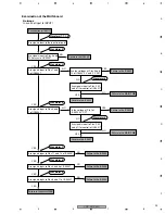
NO
YES
Failure in the CN2301 or LED PWB (failure in
the M5V line at Pin 8 of the CN2401)
NO
NO
YES
Failure in the COMM SLOT Assy (failure in the
M3.3V line at Pin 118 of the CN2303)
YES
Failure in the CN2302 or COMM SLOT IF PWB
(failure in the M3.3V line at Pin 16 of the CN2302)
NO
YES
NO
YES
Failure in the CN2302 or COMM SLOT IF PWB
(failure in the M5V line at Pin 20 of the CN2302)
Is 5 V DC output from Pin 5
of IC9502?
Failure in the MAIN PWB
(failure in the IC9502)
NO
YES
Failure in the CN4004 or COMM SLOT IF PWB
(failure in the M3.3V line at Pin 1 of the CN4004)
Failure in the CN2201 or KEY PWB (failure in the
M3.3V line at Pin 1 of the CN9011)
NO
YES
NO
Is 3.3 V DC output from Pin
4 of IC9503?
Failure in the MAIN PWB
(failure in the IC9503)
YES
NO (4.7V)
Is 0 V DC output from Pin
14 of CN8502 (AD2)?
YES
Failure in the MAIN PWB (failure in IC9501 or X9501)
Note: If IC9501 is in failure, replace the whole board.
Failure in the AD2 connector or MAIN PWB (failure in
IC9501 or X9501)
Note: If IC9501 is in failure, replace the whole board.
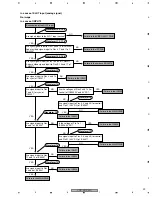
A
Turn the main power on with the cable to the CN2401 or CN2301
disconnected. Check if 5 V DC is output from Pin 8 of CN2301.
Turn the main power on with the cable to the CN2302 or CN9010
disconnected. Check if 5 V DC is output from Pin 20 of CN9010.
Turn the main power on with the COMM SLOT Assy disconnected from
CN2303. Check if 3.3 V DC is output from Pin 118 of CN2303.
Turn the main power on with the cable to the CN2302 or CN9010
disconnected. Check if 3.3 V DC is output from Pin 16 of CN9010.
Turn the main power on with the cable to the CN4004 or CN5301
disconnected. Check if 3.3 V DC is output from Pin 50 of CN5301.
Turn the main power on with the cable to the CN2201 or CN9011
disconnected. Check if 3.3 V DC is output from Pin 1 of CN9011.
Summary of Contents for PDP-42MXE20
Page 15: ...PDP 427CMX 15 5 6 7 8 5 6 7 8 C D F A B E ...
Page 19: ...PDP 427CMX 19 5 6 7 8 5 6 7 8 C D F A B E ...
Page 80: ...PDP 427CMX 80 1 2 3 4 1 2 3 4 C D F A B E 7 SCHEMATIC DIAGRAM 7 1 MAIN ASSY CPU BLOCK 1 13 ...
Page 81: ...PDP 427CMX 81 5 6 7 8 5 6 7 8 C D F A B E MAIN ASSY 1 13 CPU BLOCK Lithium Battery ...
Page 82: ...PDP 427CMX 82 1 2 3 4 1 2 3 4 C D F A B E 7 2 MAIN ASSY Interface BLOCK 2 13 ...
Page 83: ...PDP 427CMX 83 5 6 7 8 5 6 7 8 C D F A B E MAIN ASSY 2 13 Inerface BLOCK ANALOG RGB OUT ...
Page 85: ...PDP 427CMX 85 5 6 7 8 5 6 7 8 C D F A B E ...
Page 87: ...PDP 427CMX 87 5 6 7 8 5 6 7 8 C D F A B E ...
Page 89: ...PDP 427CMX 89 5 6 7 8 5 6 7 8 C D F A B E ...
Page 91: ...PDP 427CMX 91 5 6 7 8 5 6 7 8 C D F A B E ...
Page 93: ...PDP 427CMX 93 5 6 7 8 5 6 7 8 C D F A B E CAUTION ...
Page 95: ...PDP 427CMX 95 5 6 7 8 5 6 7 8 C D F A B E CAUTION ...
Page 97: ...PDP 427CMX 97 5 6 7 8 5 6 7 8 C D F A B E ...
Page 99: ...PDP 427CMX 99 5 6 7 8 5 6 7 8 C D F A B E ...
Page 101: ...PDP 427CMX 101 5 6 7 8 5 6 7 8 C D F A B E ...
Page 103: ...PDP 427CMX 103 5 6 7 8 5 6 7 8 C D F A B E ...
Page 105: ...PDP 427CMX 105 5 6 7 8 5 6 7 8 C D F A B E ...
Page 107: ...PDP 427CMX 107 5 6 7 8 5 6 7 8 C D F A B E ...
Page 108: ...PDP 427CMX 108 1 2 3 4 1 2 3 4 C D F A B E 7 14 VSIF ASSY AKM1353 VSIF ASSY ...
Page 109: ...PDP 427CMX 109 5 6 7 8 5 6 7 8 C D F A B E 1SS302 44 427 AKM1353 AKM1353 VNF1109 VNF1109 ...
Page 110: ...PDP 427CMX 110 1 2 3 4 1 2 3 4 C D F A B E 7 15 SENB ASSY ...
Page 111: ...PDP 427CMX 111 5 6 7 8 5 6 7 8 C D F A B E 7 16 SENC ASSY ...
Page 112: ...PDP 427CMX 112 1 2 3 4 1 2 3 4 C D F A B E 7 17 SEND ASSY ...
Page 113: ...PDP 427CMX 113 5 6 7 8 5 6 7 8 C D F A B E ...
Page 114: ...PDP 427CMX 114 1 2 3 4 1 2 3 4 C D F A B E 7 18 COMM SLOT ASSY ...
Page 115: ...PDP 427CMX 115 5 6 7 8 5 6 7 8 C D F A B E ...
Page 117: ...PDP 427CMX 117 5 6 7 8 5 6 7 8 C D F A B E SIDE A ANP2171 A ...
Page 118: ...PDP 427CMX 118 1 2 3 4 1 2 3 4 C D F A B E SIDE B MAIN ASSY ...
Page 119: ...PDP 427CMX 119 5 6 7 8 5 6 7 8 C D F A B E SIDE B ANP2171 A ...


