background image

Additional Information

33

En

English

Additional Information

Supplement 3

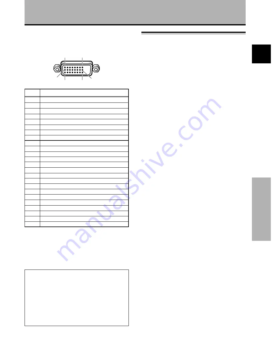
INPUT 5 (DVI female connector) pin allocation.

Signal Assignment

1

2

3

4

5

6

7

8

9

10

11

12

13

14

15

16

17

18

19

20

21

22

23

24

T.M.D.S. Data2–

T.M.D.S. Data2+

T.M.D.S. Data2/4 Shield

NC (No connection)

NC (No connection)

DDC Clock

DDC Data

NC (No connection)

T.M.D.S. Data1–

T.M.D.S. Data1+

T.M.D.S. Data1/3 Shield

NC (No connection)

NC (No connection)

+5V Power

GND

Hot Plug Detect

T.M.D.S. Data0 –

T.M.D.S. Data0 +

T.M.D.S. Data0/5 Shield

NC (No connection)

NC (No connection)

T.M.D.S. Clock Shield

T.M.D.S. Clock+

T.M.D.S. Clock–

1

8

24

17

9

16

Pin No.

Power Management is a registered trademark of Sun

Microsystems Inc.

TMDS is a registered trademark of Silicon Image Inc.

Apple and Macintosh are registered trademarks of Apple

Computer, Inc.

Microsoft is a registered trademark of Microsoft Corporation.

VGA and XGA are registered trademarks of International

Business Machines Co., Inc.

VESA and DDC are registered trademarks of Video Electronics

Standards Association.

Explanation of Terms

Aspect ratio

The TV screen’s width to height ratio is referred to as its aspect
ratio. The aspect ratio on standard TVs is 4:3 and on wide TVs or

High Definition TVs it is 16:9.

S jack (S VIDEO jack)

This jack separates and transmits the video signal as two signals;

the luminance (Y) signal and the color(C) signal. Because of this,

picture reproduction is superior to that obtained at the composite
input/output jacks.

S-video signal

The video signal is composed of two signals; the chroma signal
(color signal) which reproduces color and the luminance signal

which reproduces light and darkness. With standard video

components, these two signals are combined into one and are
handled as a video signal referred to as the “composite signal”.

The S-video signal, however, is a signal that handles these two

signals separately. Because they are not combined as in the
composite video signal, the high quality of both signals can be

retained.

Component video signal

General term for video signal format composed of the Y.C

B

.C

R

,

Y.P

B

.P

R

 and Y.B-Y.R-Y luminance color signal.

The component video signal is sometimes simply called the

“color difference signal”.

G ON SYNC

This indicates a video signal in the form of a synchronization

signal added to the G (GREEN) signal of the R.G.B signal.

VGA

VGA is short for “Video Graphics Array”.

Generally this indicates a 640 dot x 480 line resolution.

XGA

General term for “eXtended Graphics Array”.

Generally this indicates a 1024 dot x 768 line resolution.

DVI

An acronym for Digital Visual Interface, an interface standard

proposed by the Digital Display Working Group (DDWG) for

digital displays.

Published by Pioneer Corporation.
Copyright © 2001 Pioneer Corporation.
All rights reserved.

Summary of Contents for PDA-5002

Page 1: ...取扱説明書 Operating Instructions Mode d emploi Bedienungsanleitung ビデオカード VIDEO CARD CARTE VIDEO VIDEOKARTE PDA 5002 ...

Page 2: ...if a button or control on the main unit has the same or similar name as that on the remote control unit that button can be used when performing operations The following example is an actual operation that shows how one might set the horizontal and vertical positions of the screen The screens shown at each step are provided as a visual guide to confirm that the procedure is proceeding as it should ...

Page 3: ... MAIN MENU INPUT1 SELECT ENTER EXIT SET MENU PICTURE SCREEN SET UP OPTION 0 6 0 6 0 6 0 0 0 CONT RAST 0 BR R L EV EL I GHT G L EV EL B L EV EL H E NHANCE V E NHANCE R S ET E 2 Press 3 to select SCREEN SELECT ENTER EXIT SET MENU PICTURE SCREEN SET UP OPTION 0 0 POS I T I ON CL OC HAS E K 0 0 P R S ET E MAIN MENU INPUT1 3 Press 5 to select the item to be adjusted SELECT ENTER EXIT SET MENU PICTURE S...

Page 4: ...etup Connection Panel 4 RS 232C DO NOT MAKE ANY CONNECTIONS TO THIS TERMINAL This terminal is used in the factory setup 5 INPUT1 mini D sub 15 pin For connection of components that have RGB or component output jacks such as a personal computer DVD player or external RGB decoder Make sure that the connection made corresponds to the format of the signal output from the connected component pages 7 to...

Page 5: ...n The video card is provided with 3 video input connectors 1 video output connector and 2 audio input connectors Consult the pages noted in parentheses for details regarding connections to the various jacks and connectors INPUT5 DVI D jack Use to connect a computer Note This unit does not support the display of copyguard protected video signals page 11 AUDIO INPUT3 RCA Pin jacks Use to obtain soun...

Page 6: ...terations since malfunction or damage may result Take care not to modify or damage the card s internal devices in any way Before installation take precautions to eliminate static electricity on your body Do not touch the card s circuitry or devices This device has not been designed to allow reinstallation or removal after the card has once been installed on the plasma display do not attempt to rem...

Page 7: ...2 jacks After connections are made on screen setup is necessary to match the characteristics of the connected component Please see pages 14 and 15 for on screen setup after connection Do not connect anything Connect to this jack Note Components compatible with INPUT1 are also compatible with INPUT2 When making connections to INPUT1 please refer to the plasma display s Operating Instructions For th...

Page 8: ...s G B R HD VD ON SYNC H V SYNC Ô 75 2 2 Ω kΩ INPUT2 ANALOG RGB ANALOG RGB INPUT1 OUTPUT Connection to AV components Connection to AV component that has component video jacks Make component video connections for AV components such as DVD and LD players or similar components with component video output capability When connecting to INPUT1 On screen setup is necessary after connection Please see page...

Page 9: ...n signal is above 75 Ω set this switch to the 2 2 kΩ position On screen setup is necessary after connection Please see pages 14 and 15 Connection of composite SYNC analog RGB source Make composite SYNC connections for a component with output that has the vertical synchronization signal layered on top of the horizontal synchronization signal When connecting to INPUT1 On screen setup is necessary af...

Page 10: ...cording device AUDIO INPUT4 VIDEO OUTPUT R L AUDIO INPUT3 S VIDEO R L When connecting to INPUT1 ANALOG RGB ANALOG RGB INPUT1 OUTPUT Connect the cable corresponding to the shape of the input terminal on the display and the personal computer s output terminal Secure by tightening the terminal screws on both units After connecting on screen setup is necessary Please see pages 14 and 15 Note Depending...

Page 11: ...625p 575p Component RGB Composite S Video Component RGB Component RGB Personal computer Connection to INPUT5 A computer equipped with DVI output digital RGB signal can be connected to the video card s DVI connector INPUT5 DIGITAL RGB Following completing connections on screen setup is necessary See page 14 for details Notes Use a DVI D 24 pin digital only cable for the connection This unit does no...

Page 12: ...UT1 INPUT2 and INPUT5 one can be used to connect a stereo mini jack L R type plug Sound is output from both the AUDIO OUTPUT jack stereo mini jack L R and the SPEAKER terminals according to the video input selection Audio connection for component connected to INPUT1 INPUT2 or INPUT5 VD Ô 75 2 2 Ω kΩ INPUT INPUT1 2 OUTPUT AUDIO Audio connection for component connected to INPUT3 Audio input to the A...

Page 13: ...he clamp Speed clamps are designed to be difficult to undo once in place Please attach carefully To attach the speed clamps to the display Connect the speed clamps using the 4 holes marked with below depending on the situation To remove speed clamps Using pliers twist the clamp 90 and pull it outward In some cases the clamp may have deteriorated over As viewed from the rear of the display Installa...

Page 14: ...I DEO S I GNA L I NP UT 1 MAIN MENU INPUT1 9 Press SET repeatedly to select the input signal format Selection will change as follows each time SET is pressed RGB COMPONENT Setup after Connection After components have been connected to INPUT1 INPUT2 or INPUT5 on screen setup is necessary Follow the procedure described below and make settings as they apply to the type of components connected Setting...

Page 15: ...E SCREEN SET UP OPTION NT S E T T I N CL AMP POWE R G OF F P S I T I ON O M NAGEME A I NP UT I NP UT 1 L E B L A V GA L OCKED MAIN MENU INPUT1 Mode selection will change as follows each time SET is pressed 5 When the setup is completed press MENU to exit the menu screen Notes Make this CLAMP POSITION setting for each applicable input INPUT1 and INPUT2 When using this setup be sure to carefully che...

Page 16: ...the signal input will cause the menu screen to turn off If the input computer signal is not supported by the display the following message will be displayed 0 8 5 5 1 2 6 8 4 k H z f V 1 7 1 7 H z f H P O U SUP N S R ED T I NAL G CAU I O N T FUL L I NPUT 1 X 0 2 0 k H z f V 7 7 1 5 H z f H T OU N O A R F G E CAU I O N T FUL L I NPUT 1 4 Use VOLUME on the remote control unit to adjust the volume If...

Page 17: ...matically canceled about 8 minutes after the button is pressed and the volume level is adjusted to the minimum level Press VOLUME or VOLUME to adjust the volume at a desired level To confirm display settings DISPLAY Press DISPLAY on the remote control unit The currently selected input screen size and refresh rates will be displayed for about 3 seconds O D BY T DOT I NPUT 1 0 6 0 4 6 0 8 4 0 k H z ...

Page 18: ...ettings may violate the rights of authors protected under copyright law Moving the screen position upward or downward When a vista size movie etc is viewed at the ZOOM setting the image may not be centered on the screen and may extend past the edge of the screen In this case adjust the screen to an clearly viewable position using 5 Automatic screen size When a High Definition Television signal 112...

Page 19: ... screen will disappear SET or 5 2 3 can be pressed again if desired to change the zoom ratio or display position 4 Press the remote control unit s POINT ZOOM once again to cancel the point zoom operation The point zoom function will also be canceled whenever the input signal changes the menu screen is displayed or the INPUT changes Notes Whenever POINT ZOOM is selected the screen size automaticall...

Page 20: ... 5 is used SELECT CHANGE EXIT SET MENU PICTURE SCREEN SET UP OPTION AU T O S E T T I N CL AMP POWE R G OF F P S I T I ON O M NA GEME A I NP UT I NP UT 1 L E B L A V GA NT MAIN MENU INPUT1 In all other cases PICTURE SCREEN SET UP OPTION V GA AU T O S E T T I N CL AMP A UTO POWE R G OF F OF F P S I T I ON O I NP UT I NP UT 2 L E B L A MAIN MENU INPUT2 4 Press SET to confirm selection of the POWER MA...

Page 21: ...een Note Make these adjustments for each input INPUT1 to INPUT5 and signals PICTURE mode adjustment items Below are brief descriptions of the options that can be set in the PICTURE mode CONTRAST Adjust according to the surrounding brightness so that the picture can be seen clearly BRIGHT Adjust so that the dark parts of the picture can be seen clearly COLOR Adjust to the desired depth Setting to a...

Page 22: ... make more precise adjustments AUTO SET UP Display Operating Panel AUTO SET UP AUTO SET UP Remote Control Unit Manual Adjustment of Screen Position and Clock This setting can be adjusted when a computer signal is connected to INPUT1 INPUT2 or INPUT5 The settings on this page are not supported when INPUT3 or INPUT4 is selected or when a video signal is input 1 Press MENU to display the menu screen ...

Page 23: ...ward CLOCK PHASE CLOCK Adjust letter breakup or noise on the screen This setting adjusts the display s internal clock signal frequency that corresponds to the input video signal PHASE Adjust so that there is minimum flicker of screen letters or color misalignment This setting adjusts the phase of the internal clock signal adjusted by the CLOCK setting Notes When CLOCK adjustment is carried out the...

Page 24: ...UT 1 L E B L A T E S RE I NPUT 1 D N E A E C A S P 5 Press 2 3 5 to select the first desired character here C then press SET to confirm repeat this step to input up to eight desired characters SELECT SET EXIT SET MENU BACK SPACE J M K L B C D E F G H W Z X Y N O P Q R S T V U 9 0 1 2 3 4 5 6 8 7 I NP UT I NP UT 1 L E B L A T E S RE I NPUT 1 E C A S P D N E A C I Usable characters include 52 types ...

Page 25: ...for each of the inputs INPUT1 INPUT4 Reducing Video Noise DIGITAL NR Make this setting if video noise is objectionable 1 Press MENU to display the menu screen R S ET E SELECT ENTER EXIT SET MENU PICTURE SET UP OPTION 0 0 0 0 CONT RAST 0 BR C L OR I GHT O T NT I S ARP H MAIN MENU INPUT1 2 Press 2 3 to select SET UP SELECT ENTER EXIT SET MENU PICTURE SET UP OPTION V I DE O RGB AU T O S E T T I N V I...

Page 26: ...etting the PureCinema mode When the PureCinema mode is selected it functions automatically to detect video signals of movies recorded at 24 frames per second changing the scan settings to allow enjoyment of higher quality movie playback It does this by converting the video signal to progressive scan When using the PureCinema function it should odinarily be set to HQ Note however that due to the ti...

Page 27: ...elected While COLOR SYSTEM is set to AUTO and the unit is receiving an NTSC signal or when COLOR SYSTEM is set to NTSC 1 Press MENU to display the menu screen The menu screen appears R S ET E SELECT ENTER EXIT SET MENU PICTURE SET UP OPTION 0 0 0 0 CONT RAST 0 BR C L OR I GHT O T NT I S ARP H MAIN MENU INPUT4 2 Press 2 3 to select SET UP SELECT ENTER EXIT SET MENU PICTURE SET UP OPTION AU T O MOT ...

Page 28: ...RE SET UP OPTION AU T O MOT I MODE ON COL OR 3 D Y C OF F AUT O P OWER SYST EM OF F M I DD LE COL OR T M P E L OW D I G I T AL NR OF F P URE I C N MA E I NP UT L E B L A H I GH CO T N RA T S OF F MAIN MENU INPUT4 I NP UT 4 When viewing an image from INPUT1 or INPUT2 the following screen is displayed SELECT CHANGE EXIT SET MENU PICTURE SET UP OPTION I NP UT L E B L A V I DE O AU T O S E T T I N CL ...

Page 29: ... N N F AUD I O O U U F I E X D OF F POWER ND S T A ARD R T L O N CO MAIN MENU INPUT1 4 Press SET to select INPUT1 or INPUT4 The factory default setting is OFF Each time SET is pressed the selector function switches alternately as shown When OFF is selected AUTO FUNCTION is disabled After INPUT 1 or INPUT 4 is selected if a signal is detected to the selected input jack the input function will autom...

Page 30: ...N CO MAIN MENU INPUT1 3 Press 5 to select AUDIO OUT SELECT CHANGE EXIT SET MENU PICTURE SCREEN SET UP OPTION AUT O CT T I O N N F A UD I O O U U F I E X D OF F POWER ND S T A ARD R T L O N CO MAIN MENU INPUT1 4 Press SET to select the desired audio level setting The factory default setting is FIXED Each time SET is pressed the function alternates as shown When FIXED is selected the audio output vo...

Page 31: ...4 Input BNC jack Composite video signal 1 Vp p 75 Ω negative sync Output BNC jack 75 Ω with buffer INPUT 5 Input DVI D 24 pin connector Digital RGB signal DVI compliant TMDS signal INPUT 5 supports Microsoft Plug Play VESA DDC 2B standards Audio Input AUDIO INPUT for INPUT 3 Pin jack x2 L R 500mVrms more than 10 kΩ AUDIO INPUT for INPUT 4 Pin jack x2 L R 500mVrms more than 10 kΩ Accessories Label ...

Page 32: ...e etc may be necessary Picture will be enlarged but some fine detail will be hard to see Simple reproduction Fine detail will not be reproduced Screen size will be displayed as TYPE Only supported when combined with PDP 503CMX or PDP 503MXE 60Hz 56Hz 60Hz 60Hz 60Hz 60Hz 56Hz 60Hz 60Hz 60Hz Supplement 2 Resolution Dot x Line Vertical DOT BY DOT FULL PARTIAL Remarks 640x480 800 x600 852x480 1024x768...

Page 33: ...ideo signal as two signals the luminance Y signal and the color C signal Because of this picture reproduction is superior to that obtained at the composite input output jacks S video signal The video signal is composed of two signals the chroma signal color signal which reproduces color and the luminance signal which reproduces light and darkness With standard video components these two signals ar...

Reviews: