background image

19

Audio Adjustment <Main>

Source Level Adjustment <SLA> (Open state)

The SLA (Source Level Adjustment) function prevents radical leaps in volume level when
switching between sources. Settings are based on the FM volume level, which remains
unchanged.

Note:

• Since the FM volume is the control, SLA is not possible in the FM modes.
• The MW/LW volume level, which is different from the FM base setting volume level, can also be

adjusted similar to sources other than tuner.

• The head unit’s CD player, Multi-CD player and DVD player are set to the same volume adjust-

ment setting automatically.

• AUX, External 1 and External 2 are set to the same volume adjustment setting automatically.

5. Increase or decrease the level

with the 

5

/

buttons.

The display shows “+4” – “–4”.

4. Press Function button 4 on

MAIN Menu Setting Screen.

The display switches to SLA 
Adjustment Screen.

2. Press the MENU button to switch to the Main Menu.

3. Open the cover of the remote control switches to Main Menu Setting

Screen.

1. Compare the FM volume with the volume of the other source

(refer to RS-D7R (sold separately) Owner’s Manual).

Summary of Contents for ODR RS-A9

Page 1: ...Optical Digital Reference System Digital Integrated Amplifier Owner s Manual RS A9 ENGLISH ESPAÑOL DEUTSCH FRANÇAIS ITALIANO NEDERLANDS ...

Page 2: ...Menu Audio Adjustment Main 12 Main Menu 12 Switching to the Main Menu Balance Adjustment 12 Bass Treble Adjustment 13 Using the Compression 14 Adjusting the Listening Position 15 Using the Position Selector Fine Tuning the Position Effective distance Adjustment Using the Position Fine Tuning function Source Level Adjustment 19 Audio Adjustment Equalizer 20 About the Equalizer Menu 20 31 Band Graph...

Page 3: ...ly Memory Protect function 48 Display for the Person who Set Up the Audio Adjustments 49 Inputting the Name 49 Inputting Characters 49 Memory Data Memo 52 Connecting the Units 55 WARNING 55 CAUTION 55 About the setting of this unit 56 Setting the network mode Network Mode setting Setting Example 58 Example of 2 way system connection with 1 RS A9 Example of 4 way system connection with 1 RS A9 and ...

Page 4: ...perated by the remote control Opening the cover enables the SHIFT RETURN and FUNCTION buttons 1 6 inside the remote control For more details refer to the page 4 Closed state Open state 5 2 3 buttons BAND button MENU button FUNCTION buttons 1 6 RETURN button SHIFT button BAND button 5 2 3 buttons These buttons can not be used in the Audio Adjustment operation ...

Page 5: ...TION buttons 1 6 inside the unit Menu displays with cover open and closed in this system the available functions and the menu display vary depending on the condition of the remote control in use Remote Control Menu display Cover closed Closed state Cover open Open State 4 ENGLISH ESPAÑOL DEUTSCH FRANÇAIS ITALIANO NEDERLANDS ...

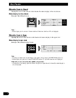
Page 6: ...pening the cover of the remote control makes the menu display to the open state Menu display in open state Example Main Menu Setting Screen Note Positions of menu items on the display correspond to the positions of FUNCTION buttons 1 6 Menu display in open state Using FUNCTION buttons 1 6 operable functions are displayed When the cover is closed in the middle of operation Closing the cover during ...

Page 7: ...unctions you can per form the same operations with the head unit however the remote control offers a number of buttons such as SHIFT MENU RETURN and FUNCTION buttons 1 6 which are not provided on the head unit And all of audio adjustment operations can only be conducted with the remote control About the Digital Network A vehicle unlike the home audio imposes several constraints upon the quality of...

Page 8: ...tons of all connected digital amps Press the system reset button when the operation status of this product RS A9 is source OFF If this product is not connected to the power supply or ACC is set to OFF the sys tem is not reset even if you press the system reset button Also confirm that the RS D7R source is OFF System resetting If you change the network mode switch setting or the system remove this ...

Page 9: ...the all clear button be sure to consult with your dealer If this product operates incorrectly first press the system reset button If this does not solve the problem press the all clear button after consulting with your dealer When you press this product s all clear button also press the RESET buttons of all con nected digital amps Connect this product RS A9 to the power supply before pressing the ...

Page 10: ...p this manual handy as a reference for operating procedures and precautions Always keep the volume low enough for outside sounds to be audible Protect the product from moisture If the battery is disconnected the preset memory will be erased and must be repro grammed In Case of Trouble Should this product fail to operate properly contact your dealer or nearest authorized Pioneer Service Station Cov...

Page 11: ...he Equalizer function for the component can make fine adjustments of sound quality for each frequency Network Network page 31 This adjusts the reproduced frequency band cross over frequency and the level of each sound range band when a multi amp system is set up It also corrects unnatural orienta tion of the sound image caused by the locations of the speakers using the Time Alignment function by s...

Page 12: ...ty Main Main Menu Equalizer Equalizer Menu Network Network Menu 3 Press the BAND button and cancel the Audio Menu Cancel the Audio Menu to return to the operations screen of the source currently in use 2 Operate the mode 1 Each press of MENU button selects the desired Audio Menu in the following order ...

Page 13: ...ion screen of the Main Menu Opening and closing the cover of the remote control refer to page 4 switches between the open and closed states of the menu display and setting screen To cancel the Main Menu press the BAND button Balance Adjustment FAD BAL CONTROL Closed state This function allows you to select a balance setting that provides ideal listening conditions in all occupied seats This functi...

Page 14: ...vel too high may result in distortion Perform Bass Treble Adjustment to adjust overall sound quality 5 Press the 5 buttons and adjust the level Holding down these buttons continues their operations with one stop at the central position 4 Press the 2 3 buttons and select a frequency point Tune to the desired frequency point BASS TREB 3 Press the FUNCTION button 1 again to choose bass BASS or treble...

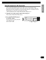
Page 15: ...d quiet sounds It is convenient to use this function when you want to hear quiet sounds more clearly CP2 Compression 2 has a larger effect than CP1 Compression 1 CP0 CP1 CP2 2 Press the FUNCTION button 2 to select the setting Pressing the button switches the mode in the following order CP0 CP1 CP2 1 Open the cover of the remote control refer to page 4 This switches to Main Menu Setting Screen 14 E...

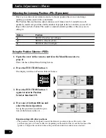
Page 16: ...Front Seat Right Using the Position Selector POSI Experimenting with other positions The position is normally designed to match the listener s position in the car However other positions may prove to be more effective depending on the model of the car and the location of the speakers Compare the sound and choose the position in which the sounds are most natural 4 Press one of buttons 2 3 5 and sel...

Page 17: ...LEV 0 30 dB 1dB 1step The smaller the level the lower the sound volume output from the speaker giving the lis tener the feeling that the speaker is moving further away The sound image thus moves in the direction in which the value for the difference in sound levels is closer to 0 Note Fine tuning can be conducted separately for each position The values set after fine tuning are stored into memory ...

Page 18: ...n completed press the RETURN button to cancel the Position Fine Tuning Screen The values are stored in memory and the display returns to Position Selector Screen 4 Press the 2 3 buttons to correct the position of the sound image Holding down these buttons continues their operations during the difference in distance tuning holding down the button moves the distance 1 54 cm 1 step ...

Page 19: ...e displayed values in memory as new values for the Time Alignment function standard values for the Position Fine Tuning function adjust any on value again by pressing the 5 buttons The displayed values are stored in memory and the difference in distance set with the Position Fine Tuning function is reset and returned to 0 When the distance has been using the Time Alignment Adjustment function Adju...

Page 20: ...es other than tuner The head unit s CD player Multi CD player and DVD player are set to the same volume adjust ment setting automatically AUX External 1 and External 2 are set to the same volume adjustment setting automatically 5 Increase or decrease the level with the 5 buttons The display shows 4 4 4 Press Function button 4 on MAIN Menu Setting Screen The display switches to SLA Adjustment Scree...

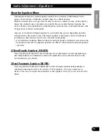
Page 21: ...rrects disturbances in frequency characteristics and creates a smooth sound quality As installation conditions differ for the left and right speakers different corrections must be made for each All two digital equalizers are able to correct the left and right speakers separately 31 Band Graphic Equalizer 31B GEQ You can perform 31 band 1 3 octave intervals level adjustments for left and right chan...

Page 22: ...te Clear function CLR Open state Memory functions of Adjusted Equalizer Curves Open state Refer to page 43 Switching to the Equalizer Menu After the title screen the display switches to the operation screen of the Equalizer Menu Opening and closing the cover of the remote control refer to page 4 switches between the open and closed states of the menu display and setting screen To cancel the Equali...

Page 23: ...ound in this range results in a lack of warmth Excessive sound dims clarity t The sound range required for the core of the sound A lack of sound in this range weakens the core An important range for keeping the overall sound quality in balance y In this range the sharp expansive sounds of the brass and electric guitar are felt However excessive sound in this range is tiring on the ears u This soun...

Page 24: ...ended The bass tends to be lacking when no subwoofer is connected Adjust the treble to a lower volume to match the weaker bass and create a well balanced sound Noises coming from the road make the bass seem weak while driving If the level is below 100 Hz adjust to a slightly greater level to maintain superb sound balance while driving When the sound is inadequate or excessive it is recommended to ...

Page 25: ...e performed in the Left Right combine mode Continued overleaf 6 Press the 5 buttons and adjust the level 5 Press the 2 3 buttons and select the desired band frequency to be adjusted 4 Press the FUNCTION button 1 and select left or right channel Only for L R mode Each press the FUNCTION button 1 switches left and right channel 3 Press the FUNCTION button 1 for two seconds and switch between Left Ri...

Page 26: ...in memory soon after the adjustments are completed Refer to page 43 for Memory operations 8 Switch between right and left to set up the equalizer curve Repeat steps 4 7 to set up equalizer curves for the left and right speakers separately 7 Adjust the other bands Repeat steps 5 and 6 to adjust to the desired sound ...

Page 27: ...o serve as the left and right central frequencies enabling level adjustments Frequency point 20 Hz 20 kHz Every 1 3 octave total 31 points Level adjustment range 12 dB 12 dB 1 dB 1 step Q select function Q factor the inclination of the equalizer curve in each band that serves as the central adjustment frequency can be selected separately Set values 1 8 2 6 4 3 7 1 dB oct The greater the value the ...

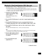
Page 28: ...tave 7 Press the 5 buttons and adjust the level 6 Press the 2 3 buttons and select the desired frequency to be adjusted 5 Press the FUNCTION button 3 and select the desired band to be adjusted Each press the FUNCTION button 3 switches to next band 4 Press the FUNCTION button 1 and select left or right channel Only for L R mode Each press the FUNCTION button 1 switches left and right channel 3 Pres...

Page 29: ...ent for the subwoofer The equalizer adjustment for the subwoofer is conducted in front when the subwoofer is connected to the front output adjusting the rear has no effect On completing adjustment Storing the equalizer curves into memory soon after completing adjustment is recommended See page 43 for memory operations 10 Switch between left and right to set up the equalizer curve Repeat steps 4 9 ...

Page 30: ...conds or more lets you make the equalizer curve for the cur rently selected mode flat When in the Left Right independent mode the equalizer curves for the left and right channels are made flat independently When the Flat function is ON the Equalizer Adjustment or Memory operations of the Equalizer curve can not be conducted 2 Press the FUNCTION button 2 switches the Flat function ON OFF FLT is dis...

Page 31: ...on operates separately for the 31 band graphic equalizer and the 3 band para metric equalizer The CLEAR function simultaneously switches ON for left and right equalizer curves It cannot be used to clear just the left or right channel 2 Press the FUNCTION button 6 for two seconds to clear the equalizer curve 1 Open the cover of the remote control in the Equalizer Menu refer to page 4 This switches ...

Page 32: ...ch frequency range by an exclusive power amplifier It is possible to reduce the modulation distortion rate since high range signals are not effected by strong signals in the low range As it is possible to select amplifiers and speakers to suit the characteristics of each fre quency range the load on each unit is reduced ensuring optimum performance Under the multi amp system it is necessary to div...

Page 33: ...s the BAND button If adjustments are difficult Adjusting the Network requires technical skills and knowledge of the amplifiers and speakers installed in the system Consult your dealer from which the products were purchased if adjustments are difficult When adjustments have already been made at your dealer the optimum setup for vehicle s particular interior has already been installed in the memory ...

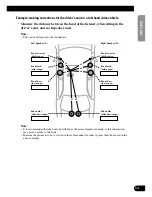
Page 34: ...eaker units In order to adjust the Time Alignment Adjustment function more easily this System allows the delay time to be set up by simply inputting the difference in the distance between speaker units the distance to be corrected The delay time will be automatically calculated by this system Although the distance from each speaker unit varies depending on the position of the listener the first se...

Page 35: ...s the measurements are made as this information may prove useful at a later date Measure the distances to be corrected in the same manner for other systems than those used in the above example Left Speaker L Front tweeter high range Front mid mid range Front bass low range Front tweeter high range Front mid mid range Front bass low range Right Speaker R Subwoofer ultrabass range Subwoofer ultrabas...

Page 36: ...ired band in the following order 4 Press FUNCTION buttons 3 or 5 and select the speaker channel to input Press the buttons to switch between left LEFT and right RIGHT 3 Press the FUNCTION button 6 and select the driver s seat posi tion Press the buttons to switch between FRONT R and FRONT L Select the position when measuring the distance to be corrected as shown on the page 34 2 Press the FUNCTION...

Page 37: ...ts for the other speaker units Repeat steps 4 6 to input the distance to be corrected for each speaker unit 6 Press the 5 buttons to input the distance to be corrected delay time Input the distance to be corrected as measured on page 34 Holding down these buttons continues their operations during distance tuning holding down the button moves the distance 1 54 cm 1 step 36 ENGLISH ESPAÑOL DEUTSCH F...

Page 38: ... range Subwoofer range 20 Hz 100 Hz 40 Hz 250 Hz 24 10 dB Low range 25 Hz 250 Hz 250 Hz 10 kHz 24 0 dB Mid range 160 Hz 10 kHz 2 kHz 20 kHz 24 0 dB High range 1 6 kHz 20 kHz 8 kHz 20 kHz 24 0 dB Slope adjustment PASS 6 12 18 24 36 48 72 dB oct Every 6 dB oct steps The slope inclination of attenuation of filter characteristics of H P F and L P F is set up Note When the slope is set as PASS the audi...

Page 39: ...ts When the position is set up for the driver s seat after adjusting the distance between the listening position and each speaker of the Time Alignment Adjustment function refer to page 33 it is rec ommended that filter adjustments be made Store the different filter characteristics into memory by the listening position set up with the Position Selector function refer to page 15 or by the source be...

Page 40: ...he filter to be adjusted Press the button to switch the band to be adjusted and high pass filter low pass filter 4 Press FUNCTION button 6 and select left Left or right Right channel only for L R mode Each press the FUNCTION button 6 switches left and right channel Even when using the Left Right combine mode you can switch to display left and right channels but adjustments are those performed in t...

Page 41: ...hat the level adjustment of the low band be made first and then the level adjustment of the mid high and subwoofer be made in that order 11 Switch between left and right channel to adjust the filter Repeat steps 4 10 to adjust the filters of left and right 10 Press FUNCTION button 4 and adjust the phase of each band Press the button to change between normal NOR and reverse REV Set up the one which...

Page 42: ...sometimes repro duce clear and high quality bass rage In this case adjust the cut off frequency to 20 40 Hz and adjust the slope to 18 72 dB oct If the subwoofer is installed in the rear tray setting up the slope of the low pass filter gently 6 12 dB oct gives the listener the feeling that the sound dwindles to the rear with a resultant dis tortion of the forward sound image position It is recomme...

Page 43: ...changing phase characteristics In general select Linear Phase Characteristics Minimum Delay Phase Characteristics Minimum Phase MIP Creating precise slope characteristics with Linear Phase Characteristics generates audio delay As a result during DVD playback for example there is a slight discrepancy between audio and video In this case by selecting Minimum Delay Phase Characteristics this product ...

Page 44: ...zer curve and network settings You can use this for example to compare the sound it provides with that provided by the settings in Base memory and Custom Memory And even if you do not perform memory operation correctly the last adjustments are stored in memory so you can memorize them again The memory operations storing recalling etc are carried out using each menu screen In this manual the memory...

Page 45: ...ss the SHIFT button The display switches to Network Memory Operation Screen for conducting memory operations Press the button again to return to the previous screen 1 Open the cover of the remote control in the Network Menu refer to page 4 2 Press the SHIFT button The display switches to Equalizer Memory Operation Screen for conducting memory operations Press the button again to return to the prev...

Page 46: ...hed ON for both Custom Memory M1 and M2 However the Protect function does not operate for M3 and LM If the Protect function is ON you cannot store information in that MEMORY button Store infor mation with another MEMORY button or cancel the Protect function Since the Protect function is cancelled after the memory to be cleared is called up the current adjusted settings are automatically stored in ...

Page 47: ...recall the memory in this manner when operating the network menu Specifying the Memory Number Directly This function can be operated when the cover of the remote control is open and the menu displays open state Stored data can be retrieved directly Recalling Memory Using Forward Reverse Order Functions of Equalizer Menu 2 Press the 5 buttons to recall the memory Press these buttons to move forward...

Page 48: ...Menu When the Flat function is turned ON it is not possible to recall memory 2 Press the FUNCTION button to recall the memory Press the FUNCTION button which corresponds to the desired memory number 1 Switch to the memory mode of each menu refer to page 44 The display switches to Memory Operations Screen of each menu ...

Page 49: ...Protect function is switched ON for M1 it is switched ON for both Custom Memory M1 and M2 However the Protect function does not operate for M3 and LM When turning the Protect function ON OFF Turning the Protect function ON OFF does not bring up anything on the display When the Protect function is turned ON and the user attempts to store new data in that memory the appears to signify that data stor...

Page 50: ...d contents are displayed Note A maximum of 20 characters can be stored The same contents are displayed on the title screen of all the Audio menus Inputting Characters Switching to the Edit Mode Characters are input in Edit Mode EDIT 3 Press the SHIFT button for two seconds to switch to Edit Mode The display switches to Character Input Screen to allow input of characters 2 Open the cover of the rem...

Page 51: ...letters numbers and sym bols with the 5 buttons 4 Switch the desired character type with FUNCTION button 1 Each press of FUNCTION button 1 changes the Character type in the fol lowing order Upper case alphabet Capital Letter Numbers and Symbols Lower case alphabet Small Letter European letters European Character such as those with accents e g á à ä ç 50 ENGLISH ESPAÑOL DEUTSCH FRANÇAIS ITALIANO NE...

Page 52: ... the audio in memory Removing the car battery clears the memory 9 The contents stored in memory are indicated on the display Switching the Audio Menu displays on the title screen the contents stored in memory 8 Press the FUNCTION button 6 or RETURN button and return to the previous mode 7 When you have completed title input memorize by pressing the FUNCTION button 5 ...

Page 53: ...equency 20 Hz 25 Hz 31 5 Hz 40 Hz 50 Hz 63 Hz 80 Hz 100 Hz 125 Hz 160 Hz 200 Hz 250 Hz 315 Hz 400 Hz 500 Hz 630 Hz 800 Hz 1 kHz 1 25 kHz 1 6 kHz 2 kHz 3 15 kHz 4 kHz 5 kHz 6 3 kHz 8 kHz 10 kHz 12 5 kHz 16 kHz 20 kHz B1 B2 M1 M2 M3 Equalizer 2 5 kHz LEFT RIGHT LEFT RIGHT LEFT RIGHT LEFT RIGHT LEFT RIGHT 52 ENGLISH ESPAÑOL DEUTSCH FRANÇAIS ITALIANO NEDERLANDS ...

Page 54: ... H P F L P F H P F LEFT RIGHT M3 L P F H P F LEFT RIGHT Level Frequency Slope Frequency Phase Slope Level Frequency Slope Frequency Phase Slope Level Frequency Slope Frequency Phase Slope Level Frequency Slope Frequency Phase Slope Level Frequency Slope S W LOW MID HIGH S W LOW MID HIGH S W LOW MID HIGH S W LOW MID HIGH S W LOW MID HIGH S W LOW MID HIGH LIN MIP LIN MIP LIN MIP LIN MIP LIN MIP ...

Page 55: ...S W LOW MID HIGH B2 S W LOW MID HIGH M1 S W LOW MID HIGH M2 S W LOW MID HIGH M3 S W LOW MID HIGH Left LEFT Right RIGHT Position Left LEFT Right RIGHT Position Left LEFT Right RIGHT Position Left LEFT Right RIGHT Position Left LEFT Right RIGHT Position Main Compression B2 B1 M1 M2 M3 ...

Page 56: ...cannot detect the cause To prevent an electric shock or short circuit during connection and installation be sure to disconnect the negative terminal of the battery beforehand Confirm that no parts are behind the panel when drilling a hole for installation of the amplifier Be sure to protect all cables and important equipment such as fuel lines brake lines and the electrical wiring from damage CAUT...

Page 57: ...speakers 2 Press the system reset button After switching the network mode setting switch when this product s operation status is source OFF press the system reset button for 1 second or more If you do not press the system reset button setting details will not change Note Press the system reset button when the operation status of this product RS A9 is source OFF If this product is not connected to ...

Page 58: ...s You are also recommended to use this setting for a 4 way system comprising this product RS A9 and one digital amp RS A7 CH A A channel HIGH Frequency range 1 6 kHz 20 kHz You can connect a tweeter CH B B channel MID Frequency range 160 Hz 20 kHz You can connect a mid range speaker You can also use a full range speaker by adjusting the network frequency BRIDGED 2CH HIGH HIGH A B 2 channel High Ra...

Page 59: ...amps in the order high mid low subwoofer mode Example of 2 way system connection with 1 RS A9 Optical cable IP BUS cable Analog signal Tweeter Low range RS D7R Sold separately This unit RS A9 Network mode setting switch HIGH LOW A B 58 ENGLISH ESPAÑOL DEUTSCH FRANÇAIS ITALIANO NEDERLANDS ...

Page 60: ...tion with 1 RS A9 and 1 RS A7 Tweeter Low range RS D7R Sold separately This unit RS A9 Mid range Address 2 Setting CHANNEL A LOW RS A7 Sold separately Subwoofer CHANNEL B SW Network mode setting switch HIGH MID A B Optical cable IP BUS cable Analog signal ...

Page 61: ...Subwoofer Optical cable must be connected to A ch Address 3 Setting CHANNEL A B LOW RS A7 Sold separately Optical cable must be connected to A ch Address 4 Setting CHANNEL A B SW RS A7 Sold separately Optical cable must be connected to A ch Optical cable IP BUS cable Analog signal When using the RS A7 with 2 channel connection be sure the RS A7 s CHANNEL A and B Network mode setting switches are s...

Page 62: ...ical input To optical input blue To IP BUS input blue blue black Fuse 25 A Refer to RS D7R owner s manual Optical out Black IP BUS out black Ground wire Black RD 223 sold separately Connect to metal body or chassis fuse 30 A 2 6 m 1 m RS A7 sold separately RS A7 sold separately Special red battery wire RD 223 sold separately After making all other connections at the amplifier connect the battery w...

Page 63: ...ction differs for each so be careful to assure and polarity and left right L R connections are correct Four channel mode Three channel mode Speaker left Speaker right Speaker wires sold separately Speaker monaural Speaker left Speaker right Speaker wires sold separately 62 ENGLISH ESPAÑOL DEUTSCH FRANÇAIS ITALIANO NEDERLANDS ...

Page 64: ...63 Connecting the Units Two channel mode Stereo Two channel mode Mono Speaker monaural Speaker wires sold separately Speaker monaural Speaker left Speaker right Speaker wires sold separately ...

Page 65: ...lifier should conform with the standards listed below If they do not conform they may catch fire emit smoke or become damaged The speaker impedance must be 2 to 8 ohms But in case of two channel and other bridge connections the speaker impedance must be 4 to 8 ohms Install and route the separately sold battery wire as far away as possible from the speaker wires Install and route the separately sol...

Page 66: ...ifier connect the battery wire terminal of the amplifier to the positive terminal of the battery 2 Twist the battery wire and ground wire 3 Attach lugs to wire ends Lugs not supplied Use pliers etc to crimp lugs to wires 4 Connect the wires to the terminal Fix the wires securely with the terminal screws Engine compart ment Interior of the vehicle Drill a 14 mm hole into the vehicle body Insert the...

Page 67: ...mp lugs to wires 3 Connect the speaker wires to the speaker output terminals Fix the speaker wires securely with the termi nal screws Secure the optical cable Secure the optical cable using the sup plied clamp as shown below When the optical cable is routed under the board When the optical cable is routed on the board Clamp Optical cable This unit Clamp Optical cable This unit Speaker wire Termina...

Page 68: ...9 RS A7 Sold separately 7 8 2 1 1 IP BUS cable supplied 2 Optical cable supplied 3 Lock tie supplied 4 Noise filter supplied 5 Noise filter supplied with RS A7 6 Lock tie supplied with RS A7 7 IP BUS cable supplied with RS A7 8 Optical cable supplied with RS A7 3 4 3 4 5 6 5 6 5 6 7 7 RS A7 Sold separately RS A7 Sold separately Noise filter Lock tie ...

Page 69: ... liquids To ensure proper installation use the supplied parts in the manner specified If any parts other than the sup plied ones are used they may damage internal parts of the amplifier or they may become loose causing the amplifier to shut down To prevent malfunction To ensure proper heat dissipation of the amplifier be sure of the following during installation Allow adequate space above the ampl...

Page 70: ...Install this unit to the vehicle Never install this unit directly to the chassis 2 Attach the terminal cover to prevent short circuit Terminal cover screws Hexagonal wrench Large Tapping screws 5 20 mm Drill a 3 5 mm diameter hole Floor mat ...

Page 71: ...t authorized Pioneer Service Station Checklist Symptom Cause Remedy Page No Operation The battery is not Connect the battery connected A red lead is not Connect all red leads 61 properly connected to the battery terminal 65 supplied with constant power regardless of the ignition switch position after running them through the vehicle s fuse unit A black lead ground is Firmly connect all the black 6...

Page 72: ...10 kHz 1 3 oct Gain 0 dB 24 dB 0 5 dB MID HPF frequency 160 Hz 10 kHz 1 3 oct LPF frequency 2 kHz 20 kHz 1 3 oct Gain 0 dB 24 dB 0 5 dB HIGH HPF frequency 1 6 kHz 20 kHz 1 3 oct LPF frequency 8 kHz 20 kHz 1 3 oct Gain 0 dB 24 dB 0 5 dB Slope PASS 6 12 18 24 36 48 72 dB oct PASS no pass HPF High channel Phase NORMAL REVERSE Time alignment H M L ch 0 192 5 cm 0 77 cm SW ch 0 385 cm 1 54 cm Position ...

Page 73: ...ong Beach California 90801 1540 U S A TEL 800 421 1404 PIONEER EUROPE NV Haven 1087 Keetberglaan 1 B 9120 Melsele Belgium TEL 0 3 570 05 11 PIONEER ELECTRONICS ASIACENTRE PTE LTD 253 Alexandra Road 04 01 Singapore 159936 TEL 65 6472 7555 PIONEER ELECTRONICS AUSTRALIA PTY LTD 178 184 Boundary Road Braeside Victoria 3195 Australia TEL 03 9586 6300 PIONEER ELECTRONICS OF CANADA INC 300 Allstate Parkw...

Reviews: