FEATURES
120W + 120W Power Amplifier with a Wide
Frequency Band and Low Distortion
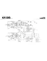
The first stage of the M-25 adopts a dual transistor
differential amplifier with a current mirror as the load for a
superb stability and gain right from the lowest low fre-
quencies to the highest high frequencies. The pre-driver
stage consists of a voltage amplifier with a constant current
circuit as the load, and this makes for a significant
improvement in the degree of use of the power voltage, and
also for a satisfying gain and linearity. The power stage
features a Class-AB pure complementary parallel push-pull
circuit with a three-stage Darlington connection. A newly
developed power transistor called a "Ring Emitter
Transistor" (RET) has been introduced into the new
Class-AB circuitry. This feature guarantees an ultra wide
frequency range which turns the attributes of the RET to
maximum advantage, and also a superior low-distortion
response whatever the power rating — across an ultra-low
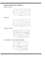
to full power spectrum. The M-25 delivers
Continuous Power Output of 120 watts* per
channel, min., at 8 ohms from 5 Hertz to
30,000 Hertz with no more than 0.01% total
harmonic distortion.
In particular, the Class-AB SEPP circuit functions as a
Class-A circuit which is highly rated on account of its hi-
fidelity sound reproduction capabilities with low power
outputs (up to 3W/8-ohms). This means that you can enjoy
the final sound as you would from a Class-A amplifier.
Finally, the pre-driver section contains an over-drive limiter
and a power limiter for protecting the power transistors.
This helps to greatly improve the reliability.
Twin Transformer Power Supply for
Excellent Separation
The M-25 is symmetrically designed with completely
separate heavyweight class power supplies for each channel.
Each employs large-capacity capacitors (two 22,000uF for
each channel) which not only feature excellent regulation
but also have plenty of reserve. Along with the wide-band
frequency response, they ensure a superior channel separa-
tion and a reproduction of sound which is both clear and
full of latent energy. There is also a surge-killer circuit to
keep the inrush current from the power transformers as
well as the high current which charges the electrolytic
capacitors to the bare minimum, and this feature reduces
the load on all of the related parts.
2
Highly Dependable Protective Circuitry
The M-25 employs a relay type of protective circuit
which is equipped with a current detector and an
overcurrent detector. This circuit is designed to protect the
speakers from unforeseen accidents caused by the genera-
tion of current in the output, or from shortcircuiting of the
speaker terminals owing to faulty contacts, as well as the
power transistors by releasing the output circuitry
momentarily. Moreover, the output circuit relay is for 4-
circuit high current uses and all the circuits are connected in
parallel for enhanced reliability. This circuitry can also be
counted on to perform muting when the power switch is
flipped between ON and OFF.
Carefully Selected, High-quality Parts
Each and every part which makes up the M-25 has been
singled out for its quality so that only the best is finally
chosen. Among the parts employed are gold-plated input
and speaker terminals, printed circuit boards of paper
epoxy resin with a high insulation resistance, and printed
circuit boards using 70u
thick copper foil, low-resistance
pure copper plates for parallel connections and for the
grounding wire, and non-inductive cement resistors.
Esthetically Satisfying and Full-bodied Design
The visual appeal of the power transistors and heat sinks
mounted on a broad-based silver-toned aluminum die-cast
chassis is what you would expect from a top-quality power
amplifier. Just one look at the M-25 is enough to convince
you of its tremendous power and stability.
*Measured pursuant to Federal Trade Commission's Trade
Regulation Rule on Power Output Claims for Amplifiers.


