background image

27

5

6

7

8

F

E

D

C

B

A

5

6

7

8

KEH-P2030/XM/UC

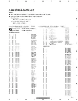
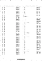
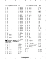
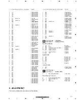
5. ELECTRICAL PARTS LIST

NOTE:

-

Parts whose parts numbers are omitted are subject to being not supplied.

-

The part numbers shown below indicate chip components.

Chip Resistor

RS1/

_

S

___

J,RS1/

__

S

___

J

Chip Capacitor (except for CQS.....)

CKS....., CCS....., CSZS.....

Unit Number : CZW5537(KEH-P2030)
Unit Name

: Tuner Amp Unit

MISCELLANEOUS

IC

1

IC

000974490

IC

2

IC

PST3434UL

IC

150

IC

LC72135M

IC

200

IC

BA4560F

IC

300

IC

PML010A

IC

400

IC

HA12187FP

IC

500

IC

TDA7384

IC

600

IC

TPD1018F

Q

100

Transistor

DTC124EK

Q

102

Transistor

DTA123YKA

Q

150

Transistor

2SK536

Q

151

Transistor

DTA123YKA

Q

250

Transistor

2SA1706

Q

251

Transistor

DTC114EK

Q

350

Transistor

IMH3A

Q

351

Transistor

DTA124EK

Q

400

Transistor

2PB709A

Q

401

Transistor

DTC114EK

Q

500

Transistor

DTC124EK

Q

501

Transistor

IMD2A

Q

600

Transistor

2PD601A

Q

601

Transistor

2PD601A

Q

602

Transistor

2SB1181F5

Q

603

Transistor

2PD601A

Q

604

Transistor

2SD2396

Q

605

Transistor

2PD601A

Q

606

Transistor

2SA2112

Q

607

Transistor

DTC114EK

Q

800

Transistor

2PB709A

D

1

Diode

1SS355

D

100

Diode

1SS355

D

200

Diode

1SS133

D

250

Diode

11ES2

D

500

Diode

DAN202U

D

600

Diode

11ES2

D

601

Diode

11ES2

D

602

Diode

HZS7L(C2)

D

603

Diode

HZS7L(A1)

D

604

Diode

11ES2

D

605

Diode

11ES2

D

606

Diode

11ES2

D

607

Diode

HZS6L(B2)

D

608

Diode

HZS9L(C1)

D

609

Diode

HZS9L(A2)

D

800

Diode

1SS133

D

801

Diode

1SS133

D

802

Diode

1SS133

D

803

Diode

1SS133

D

804

Diode

1SS133

D

805

Diode

1SS133

L

1

Inductor

LAU2R2J

L

100

Ferri-Inductor

LAU100J

L

101

Coil

CZT2930

L

102

Ferri-Inductor

LAU4R7J

L

103

Ferri-Inductor

LAU4R7J

L

151

Ferri-Inductor

LAU4R7J

L

300

Ferri-Inductor

LAU4R7J

L

400

Inductor

LAU2R2J

L

600

Choke Coil 600µH

CTH1221

L

800

Ferri-Inductor

LAU100J

X

1

Crystal Resonator 4.194304MHz

CZS2918

X

150

Crystal Resonator 7.200MHz

CZS2920

TU

100

Tuner Unit

CZW5534

DSP 100

Surge Protector

DSP-201M-A11F

RESISTORS

R

1

RS1/16S102J

R

2

RS1/16S102J

R

3

RS1/16S102J

R

4

RS1/16S102J

R

5

RD1/4PU102J

R

6

RD1/4PU102J

R

7

RS1/16S102J

R

8

RS1/16S473J

R

9

RD1/4PU222J

R

10

RS1/16S682J

R

11

RS1/16S473J

R

12

RS1/16S0R0J

R

13

RS1/16S473J

R

15

RS1/16S104J

R

16

RD1/4PU102J

R

102

RS1/16S101J

R

103

RS1/16S101J

R

105

RS1/16S222J

R

110

RS1/16S103J

R

113

RS1/16S152J

R

114

RS1/16S222J

R

115

RS1/16S223J

R

120

RS1/16S103J

R

121

RS1/16S103J

R

122

RS1/16S183J

R

123

RS1/16S183J

R

124

RS1/16S104J

R

125

RS1/16S223J

R

151

RS1/16S222J

R

152

RS1/16S332J

R

153

RS1/16S181J

R

154

RS1/16S222J

R

156

RS1/16S513J

R

157

RS1/16S103J

R

159

RS1/16S102J

R

160

RS1/16S102J

R

162

RS1/16S471J

R

200

RS1/16S473J

R

201

RS1/16S473J

R

202

RS1/16S101J

=====Circuit Symbol and No.===Part Name

Part No.

---

------

------------------------------------------

=====Circuit Symbol and No.===Part Name

Part No.

---

------

------------------------------------------

-------------------------

A

Summary of Contents for KEH-P2035

Page 1: ...ortant symbols for good services This service manual does not describe the CD test mode For the operations in the CD test mode refer to the CD player s Service manual CONTENTS SAFETY INFORMATION 2 1 SPECIFICATIONS 3 2 EXPLODED VIEWS AND PARTS LIST 6 2 1 PACKING 6 2 2 EXTERIOR 8 2 3 CASSETTE MECHANISM 10 3 BLOCK DIAGRAM AND SCHEMATIC DIAGRAM 12 3 1 BLOCK DIAGRAM 12 3 2 OVERALL CONNECTION DIAGRAM 14...

Page 2: ...ng mode and shipping screws To protect the product from damages or failures that may be caused during transit the shipping mode should be set or the shipping screws should be installed before shipping out in accordance with this manual if necessary 1 Product safety You should conform to the regulations governing the product safety radio and noise and other regulations and should keep the safety du...

Page 3: ...3 5 6 7 8 F E D C B A 5 6 7 8 KEH P2030 XM UC 1 SPECIFICATIONS KEH P2030 XM UC Backup current Less than 3 mA 4 76 cm sec 0 14cm sec 0 05cm sec ...

Page 4: ...4 1 2 3 4 1 2 3 4 F E D C B A KEH P2030 XM UC KEH P2035 XM ES 4 76 cm sec 0 14cm sec 0 05cm sec Backup current Less than 3 mA ...

Page 5: ...5 5 6 7 8 F E D C B A 5 6 7 8 KEH P2030 XM UC ...

Page 6: ...6 1 2 3 4 1 2 3 4 F E D C B A KEH P2030 XM UC 2 EXPLODED VIEWS AND PARTS LIST 2 1 PACKING 16 3 4 18 2 17 1 7 5 12 13 11 10 15 14 8 6 9 ...

Page 7: ...assembly For the applying amount of lubricants or glue follow the instructions in this manual In the case of no amount instructions apply as you think it appropriate Owner s Manual Installation Manual Model Part No Language KEH P2030 XM UC CZR2953 English French Spanish CZR2954 English French Spanish KEH P2035 XM ES CZR2955 English Spanish Portuguese B Arabic Traditional chinese CZR2956 English Sp...

Page 8: ...8 1 2 3 4 1 2 3 4 F E D C B A KEH P2030 XM UC 2 2 EXTERIOR ...

Page 9: ... CZK2951 32 Connector CN101 CZK2954 33 Rear Chassis CZN6834 34 Heat Sink CZN6835 35 Keyboard Unit CZW5543 36 Connector CN900 CKS3580 37 LCD LCD900 CZA5579 38 Holder CZN6743 39 Connector CZN6745 40 Light Plate CZN6760 41 Lighting Conductor CZN6846 42 Rubber CZN6847 43 Sheet CZN6848 44 Screw BMZ26P040FMC 45 Bracket CZN6738 46 Mechanism CZX5514 47 Detach Grille Assy KEH P2030 CZX5548 Detach Grille As...

Page 10: ...10 1 2 3 4 1 2 3 4 F E D C B A KEH P2030 XM UC 2 3 CASSETTE MECHANISM ...

Page 11: ...0363 4003 13 Screw 2 1032 0070 C2 14 Tape Guide 1 0038 2018 15 Link 1 0363 2006 16 Pinch Arm R Assy 1 0036 6013 17 Spring 1 0363 4004 18 Motor Assy M1 X 0363 7006 19 Power Switch S1 1 0363 7005 20 Mute Switch S2 1 0363 7001 21 Screw 213317040 C2 22 Screw 2 1032 0025 C2 23 Arm Assy X 0363 6003 24 Slide Switch S3 1 0363 7002 25 SW PWB 1 0363 7008 26 Belt 1 0036 5018 27 Screw 213820030 C2 28 Belt 1 0...

Page 12: ...7 VC2 Q3 VR2 GND TP1 T1 FM DET AM RF Q1 AM OSC FM RF FM OSC 1 2 4 5 7 10 46 45 35 36 37 32 31 30 29 28 27 26 24 23 20 19 49 51 52 53 54 56 57 59 60 62 63 64 58 55 15 16 34 Q102 COM9V Q151 E C B U5V IC150 LC72135M 8 7 6 5 2 1 1 3 8 9 16 1 20 14 13 15 7 7 6 2 CN100 ANT 1 5 TUNER AMP UNIT TUNER UNIT A C SWITCH PCB M1 MOTOR ASSY M S1 TAPE TUN S2 MUTE HD1 HEAD 1 3 LCH MOTOR CN250 CN200 Q250 Q251 B U14V...

Page 13: ...5 30 Q800 B U5V 2 8 CN800 DGND ILLGND ST SD SL MUTE SYSPW X2 X1 BSENS B REM ASENS TX RX ASENB0 RESET 3 SW5V 7 1 6 39 SWVDD KEYBOARD UNIT Q605 000974490 SYSTEM CONTROLLER Q400 Q401 B U14V IC300 PML010A ELECTRONIC VOLUME 1 8 7 11 BUS BUS SWDB BUSL IC400 HA12187FP 6 5 5 1 2 6 5 2 4 36 IN4 L IN4 L IN1L IN3L SW5V 11 10 OUT_RL OUT_FL BUSL IC500 TDA7384 UC POWER AMP 15 IN3 RL 11 IN1 FL 4 STB TA8277H ES 7...

Page 14: ... RCH LCH 8V 5V 5V 14V GND S2 ROUT S1 BUS BUS VCC STB BUSL BUSR BUSR BUSL SWDB BUS BUS 8V 14V DSENS DGND SW5V NC KYDT DPDT ILL B ILLGND 2 3 4 5 8 6 7 1 9 11 10 ASENBO XIN CE DI CLK DO NC XOUT VSS NC NC NC PD VDD NC FM_IN LO DX AM_IN SEEK FM AM IF_IN CN101 AR100 61 1 1 XT2 C309 R22 C306 10P C313 2R2K R805 C307 R1 C301 R22 C305 1K R7 10P C315 R22 C303 TP1 R22 C304 10P C316 GND2 R10 10P C314 R12 4R7uH...

Page 15: ...2 D601 R0022 C353 HZS6L B2 D607 D602 HZS9L A2 D609 R01 C610 11ES2 D509 100 R504 11ES2 D605 47K R353 DTA124EK Q351 22K R605 270 R610 2PD601A Q605 11ES2 D503 2PD601A Q600 11ES2 D604 47K R601 R047 C604 GND1 47K R352 R47 C504 R1 C513 10K R500 HZS9L C1 D608 3 2 1 6 5 4 R1 C601 3 2 1 4 5 6 1R8K R616 1R8K R615 100 10 C612 100 10 C609 GND1 10K R612 IMH3A Q350 1 2 3 4 5 6 1 2 3 4 5 6 8 9 10 7 CN350 2SA2112...

Page 16: ...SEG5 SEG4 SEG3 SEG1 SEG2 COM3 COM0 COM2 COM1 KDT1 KDT0 KST0 KST1 KST2 KST3 KS COM0 COM1 COM3 SEG2 SEG1 SEG4 SEG3 SEG12 SEG6 SEG11 SEG5 SEG9 SEG10 SEG8 SEG7 SEG28 SEG20 SEG14 SEG27 SEG21 SEG25 SEG26 SEG24 SEG23 SEG13 SEG22 SEG17 SEG18 SEG16 SEG15 SEG34 SEG30 SEG31 SEG32 SEG33 SEG35 SEG37 SEG29 SEG36 SEG38 COM2 SEG19 SEG4 SEG3 SEG2 SEG1 SEG0 COM3 COM2 COM1 COM0 LCDB KST3 KST2 KST1 KST0 KDT0 KDT1 REM...

Page 17: ...902 SW921 SW910 SW912 SW901 SW918 SW900 SW926 SW928 SW929 SW920 SW907 SW916 SW905 SW924 SW931 SW922 SW917 SW909 SW904 SW915 SW925 SW911 SW906 SW913 SW908 SW930 CN900 1 2 3 4 5 6 7 8 PL902 PL901 PL900 KDT3 KDT2 KST4 KDT0 KDT1 KDT2 KST4 KDT3 KST0 KST1 KST2 KST3 DESNS DGND SW5V NC KYDT DPDT ILL B ILLGND LOCAL BTB 4 1 VOL AUDIO BAND 6 2 SOURCE LOUD 3 DISP CLOCK 5 VOL ...

Page 18: ...GND2 Rch Lch GND Rch Lch S1 TAPE TUN 1 0363 7005 S2 MUTE 1 0363 7001 S3 1 0363 7002 FWD REV Rch Lch TUNER AMP UNIT A FF REW GND1 N R MOTOR MOTOR TAPE IN GND3 8 5 4 3 2 1 6 7 8 5 4 3 2 1 6 7 M 2 1 3 2 1 3 C A 1 2 3 4 1 2 3 4 F E D C B A KEH P2030 XM UC 3 4 CASSETTE MECHANISM C ...

Page 19: ...19 5 6 7 8 F E D C B A 5 6 7 8 KEH P2030 XM UC ...

Page 20: ... of PCB diagrams Capacitor Connector P C Board Chip Part SIDE A SIDE B A TUNER AMP UNIT A C 17 18 CN900 ES E E E B 1 2 3 4 5 6 7 8 9 10 11 1 2 3 4 5 6 7 8 9 10 11 12 13 14 15 16 1 3 5 7 2 4 6 8 1 2 3 4 5 6 7 8 BUS CONNECTOR CORD ASSY R406 R408 R604 R800 R801 R802 R610 CN400 R612 R615 R616 CN600 CN800 R252 R253 R256 C605 C608 C609 C612 CN250 C3 C4 D600 D601 D602 D603 D604 D605 D607 D608 D609 D800 D...

Page 21: ...12 13 14 15 16 17 18 C IC Q 1 2 3 4 5 6 7 8 9 10 11 12 13 14 16 18 20 22 24 15 17 19 21 23 25 1 2 3 PRE OUT 3 ANTENNA CN200 TU100 C206 C207 C211 C213 R252 R253 C600 D200 L100 L101 L102 L103 D600 L300 D601 D606 DSP100 L151 CN100 C101 C103 C300 C302 C508 R16 C511 CN350 R5 R6 C151 BP C154 C158 C350 C351 X150 ET100 IC500 ...

Page 22: ... C500 C501 C502 C503 C310 C504 C311 C505 C312 C506 C313 C507 C120 C314 C121 C315 C509 C122 C316 C510 C512 C513 C515 C153 C155 C156 C157 C159 C352 C353 D100 C161 C162 D500 IC300 R R4 R402 R403 R210 R404 R211 R405 R212 R213 R214 R611 JC1 R R102 R103 R302 R303 R110 R304 R305 R113 R114 R115 R500 R501 R502 ES R503 R504 R120 R121 R122 R123 R124 R125 R151 R152 R153 R154 R156 R157 R159 R350 R351 R352 R353...

Page 23: ...610 C611 C1 C2 C6 C7 C8 Q501 IC400 IC600 IC2 Q400 Q401 D500 Q600 Q602 Q603 Q605 Q607 Q800 Q251 R400 R401 R402 R403 R404 05 R407 R409 R600 R601 R602 R603 R410 R411 R605 R412 R606 R413 R607 R414 R608 R415 R609 R416 R803 R804 R805 R806 R613 R807 R614 JC3 R250 R251 R254 R255 R505 1 2 3 4 R10 R11 R12 R13 R14 TP1 TP2 R7 R8 1 3 4 6 E E E E E E E E E E R417 D1 IC1 Q601 1 1 1 1 ...

Page 24: ...900 1 2 7 8 CN900 3 5 4 6 CN800 PL902 R900 R901 R902 C900 C901 D900 B A B KEYBOARD UNIT CLOCK LOUD SW908 VOL VOL SW931 SOURCE DISP 1 2 3 4 5 6 42 40 35 SW915 SW916 SW921 SW922 SW927 SW928 SW925 SW926 SW917 SW918 SW923 SW924 SW906 SW907 SW913 SW914 SW919 SW920 SW904 SW905 SW929 SW930 SW911 SW912 ...

Page 25: ... 5 6 7 8 F E D C B A 5 6 7 8 KEH P2030 XM UC B SIDE A SIDE B RN901 17 16 1 32 33 48 49 64 R903 RN900 X900 IC900 PL901 LCD900 35 30 25 20 15 10 5 1 SW900 LOCAL SW901 SW910 BAND SW903 SW902 BTB AUDIO SW909 ...

Page 26: ...6 1 2 3 4 1 2 3 4 F E D C B A KEH P2030 XM UC 4 3 CASSETTE MECHANISM C SWITCH PCB 2 3 1 HD1 HEAD Rch Lch M1 MOTOR ASSY S1 TAPE TUN S2 MUTE 8 5 4 3 2 1 6 7 M 1 2 3 S3 FWD REV S3 A CN250 A CN200 3 2 1 C C ...

Page 27: ...S2 D 605 Diode 11ES2 D 606 Diode 11ES2 D 607 Diode HZS6L B2 D 608 Diode HZS9L C1 D 609 Diode HZS9L A2 D 800 Diode 1SS133 D 801 Diode 1SS133 D 802 Diode 1SS133 D 803 Diode 1SS133 D 804 Diode 1SS133 D 805 Diode 1SS133 L 1 Inductor LAU2R2J L 100 Ferri Inductor LAU100J L 101 Coil CZT2930 L 102 Ferri Inductor LAU4R7J L 103 Ferri Inductor LAU4R7J L 151 Ferri Inductor LAU4R7J L 300 Ferri Inductor LAU4R7J...

Page 28: ...1 4PU271J R 611 RS1 16S152J R 612 RD1 4PU103J R 613 RS1 16S223J R 614 RS1 16S103J R 615 RD1 4PU182J R 616 RD1 4PU182J R 800 RD1 4PU222J R 801 RD1 4PU222J R 802 RD1 4PU222J R 803 RS1 16S473J R 804 RS1 8S4R7J R 805 RS1 16S222J R 806 RS1 16S223J R 807 RS1 16S222J JC 1 RS1 16S0R0J JC 3 RS1 16S0R0J CAPACITORS C 1 CCSRCH150J50 C 2 CKSRYB104K50 C 3 CEAL100M16 C 4 CEAL2R2M50 C 6 CCSRCH150J50 C 7 CCSRCH150...

Page 29: ... 350 Transistor IMH3A Q 351 Transistor DTA124EK Q 400 Transistor 2PB709A Q 401 Transistor DTC114EK Q 500 Transistor DTC124EK Q 501 Transistor IMD2A Q 600 Transistor 2PD601A Q 601 Transistor 2PD601A Q 602 Transistor 2SB1181F5 Q 603 Transistor 2PD601A Q 604 Transistor 2SD2396 Q 605 Transistor 2PD601A Q 606 Transistor 2SA2112 Q 607 Transistor DTC114EK Q 800 Transistor 2PB709A D 1 Diode 1SS355 D 100 D...

Page 30: ...1 16S821J R 352 RS1 16S473J R 353 RS1 16S473J R 400 RS1 16S821J R 401 RS1 16S821J R 402 RS1 16S223J R 403 RS1 16S223J R 404 RS1 16S102J R 405 RS1 16S102J R 406 RD1 4PU101J R 407 RS1 16S620J R 408 RD1 4PU101J R 409 RS1 16S222J R 410 RS1 16S223J R 411 RS1 16S472J R 412 RS1 16S102J R 413 RS1 16S102J R 414 RS1 16S102J R 415 RS1 16S473J R 416 RS1 16S473J R 500 RS1 16S103J R 501 RS1 16S103J R 502 RS1 16...

Page 31: ...CKSQYB474K25 C 504 CKSQYB474K25 C 505 CKSQYB474K25 C 506 CKSQYB474K25 C 507 CKSQYB474K25 C 508 CEAL100M16 C 509 CKSQYB225K10 C 510 CKSQYB225K10 C 511 CEAL330M10 C 512 CKSRYB104K50 C 513 CKSRYB104K50 C 514 CKSQYB224K50 C 515 CKSRYB473K50 C 600 3300µF 16V CCH1018 C 601 CKSRYB104K50 C 602 CKSRYB102K50 C 603 CKSQYB104K50 C 604 CKSRYB473K50 C 605 CEAL470M16 C 606 CKSRYB103K50 C 607 CKSRYB103K50 C 608 4...

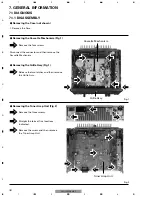
Page 32: ...screws Remove the three screws 1 Remove the Case Removing the Case not shown Disconnect the connector and then remove the Cassette Mechanism Removing the Grille Assy Fig 1 2 Release the two latches and then remove the Grille Assy 1 1 2 2 Cassette Mechanism Grille Assy 1 1 1 2 2 2 3 Tuner Amp Unit 2 Straight the tabs at five locations indicated 3 Remove the screw and then remove the Tuner Amp Unit ...

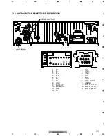
Page 33: ...1 10 11 12 9 1 RR 2 RL 3 RL 4 FL 5 FL 6 FR 7 FR 8 GND 9 BACK UP 10 B REMOTE 11 ACC 12 RR 8 9 10 11 5 6 7 1 2 3 4 1 BUS 2 GND 3 GND 4 NC 5 BUS 6 GND 7 BUS INPUT 8 ASENB 9 BUS R INPUT 10 BUS R INPUT 11 BUS L INPUT 1 0 1 0 ANTENNA REAR OUTPUT 7 1 2 CONNECTOR FUNCTION DESCRIPTION ...

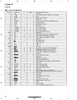
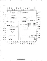
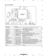
Page 34: ...0 ST I FM stereo input 31 32 NC Not used 33 VSS1 GND 34 35 NC Not used 36 SW5V O N PLL IC power supply control output 5V 37 FM AM O N FM AM band select pin H AM L FM 38 TUON O N Tuner power supply control output 39 SWVDD O N Grille power supply control output 5V 40 45 NC Not used 46 TAPEIN I Tape insert sense input 47 NC Not used 48 FFREW I FF REW sense input 49 PCL O C Clock adjustment output 50 ...

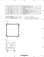
Page 35: ...me I O Format Function and Operation 70 X1 I Crystal oscillator connection pin 71 IC GND 72 XT2 Not used 73 TESTIN I Test program mode input 74 VDD0 Power supply 75 AVREF0 I A D converter reference voltage terminal 76 SL I Signal level input 77 MODELIN I Distinction input 2 0 3 0V 78 80 NC Not used Format C N Meaning C MOS N Channel open drain 1 20 60 41 21 40 80 61 000974490 PST3434UL ...

Page 36: ...36 1 2 3 4 1 2 3 4 F E D C B A KEH P2030 XM UC PD6340A ...

Page 37: ...Ground for the front end section 9 GND FM IF AM ground Ground for the FM IF AM section 10 N C Not used 11 FM AM Vt I Tuning voltage Connect to the PLL circuit 12 FM AM OSC BUFF O OSC buffer output Connect to the PLL circuit 13 L OUT O L channel output FM stereo L ch signal output or AM audio output 14 R OUT O R channel output FM stereo R ch signal output or AM audio output 15 FM AM SD OUT O Statio...

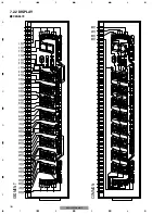
Page 38: ... SEG37 SEG36 SEG35 SEG34 SEG33 SEG32 SEG31 SEG30 SEG29 SEG28 SEG27 SEG26 SEG25 SEG24 SEG23 SEG22 SEG21 SEG20 SEG19 SEG18 SEG17 SEG16 SEG15 SEG14 SEG13 SEG12 SEG11 SEG10 SEG9 SEG8 SEG7 SEG6 SEG5 SEG4 SEG3 SEG2 SEG1 COM3 COM2 COM1 COM0 COMMON 7 2 2 DISPLAY CZA5579 ...

Page 39: ...SPW H Pin 54 BSENS L ASENS L 300ms 300ms In case of the above signal the communication with Grille microcomputer may fail If the time interval is not 300msec the oscillator may be defective Completes power on operation After that proceed to each source operation IPPW H Pin 59 ASENBO H Pin 58 Starts communication with Grille microcomputer 7 3 OPERATIONAL FLOW CHART ...

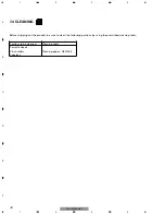
Page 40: ... P2030 XM UC 7 4 CLEANING Before shipping out the product be sure to clean the following portions by using the prescribed cleaning tools Portions to be cleaned Cleaning tools Cassette heads Pinch rollers Cleaning paper GED 008 Capstans ...

Page 41: ...41 5 6 7 8 F E D C B A 5 6 7 8 KEH P2030 XM UC 8 OPERATIONS ...

Page 42: ...42 1 2 3 4 1 2 3 4 F E D C B A KEH P2030 XM UC ...

Page 43: ... About the fixing screws for the front panel If you do not operate the Detaching and Replacing the Front Panel Function use the supplied fixing screws and fix the front panel to this unit Fixing screw CBA1488 KEH P2030 XM UC CXX1066 KEH P2035 XM ES ...

Page 44: ...en Green black Gray black Violet Violet black Front speaker Rear speaker Left With a 2 speaker system do not connect anything to the speaker leads that are not connected to speakers Yellow To terminal always supplied with power regardless of ignition switch position Black ground To vehicle metal body Red To electric terminal controlled by ignition switch 12 V DC ON OFF Power amp sold separately An...

Reviews: