HTZ-7, HTZ-C7, HTZ-SW7, HTZ-ST7
104
No.
Symbol
Name
I/O
Description
1
G1/A1
–––––
OUT
––––––––––
2
G0/A0
–––––
OUT
––––––––––
3
NC
–––––
––
5V
4
PE0/INT0/EC0
–––––
IN
5V
5
PE1/INT1/EC1
AC_PULSE
IN
AC pulse input (interrupt use)
6
PE2/INT2
SYSBUS_CLOCK
IN
System bus clock input (interrupt use)
7
PE3/INT3/NM1
AC3_REQ
IN
Communication request from the AC3 board, “L”: Communication request (interrupt use)
8
PE4/RMC
REM_IN
IN
Remote control input
9
PE5
TEST_MODE
IN
Test mode when L at the time of power ON
10
PE6/PWM
–––––
OUT
––––––––––
11
PE7/TO/ADJ
–––––
OUT
––––––––––
12
PC0/KR0
–––––
OUT
––––––––––
13
PC1/KR1
FL_DATA
OUT
FL driver data
14
PC2/KR2
DEM_LOCK
IN
When the modulator IC is locked to the RF signal, “L” Input
15
PC3/KR3
DIR_LOCK
IN
When DIR is locked to the digital input signal, “L” Input
16
PC4/KR4
SYSBUS_DI
IN
System bus data input [ for ID (priority) confirmation ]
17
PC5/KR5
SYSBUS_DO
IN/OUT
System bus data output
18
PC6/KR6
SYSBUS_REQ
IN/OUT
System bus REQ I/O (input except at the time of transmission)
19
PC7/KR7
FL_CLK
OUT
FL diver clock
20
PB0/CINT
FL_CE
OUT
FL driver address/data status
21
PB1/CS0
AC3_CS
OUT
Chip selection for AC-3 board communication
22
PB2/SCK0
AC3_CLK
OUT
Serial clock for AC-3 board communication
23
PB3/SI0
AC3_OUT
IN
Serial data input for AC-3 board communication
24
PB4/SO0
AC3_DATA
OUT
Serial data output for AC-3 board communication
25
PB5/SCK1
DISP_CLOCK
IN
Clock input for display communication
26
PB6/SI1
DISP_DATA
IN
Data input for display communication
27
PB7/SO1
DISP_REQ
IN
REQ output for display communication
28
AVref
–––––
––
5V
29
PA0/AN0
HP_SW
IN
Headphone insertion detection
30
PA1/AN1
DC DETECT
IN
Power supply trouble detection AD
31
PA2/AN2
TEMP_HI1
IN
Temperature rise detection, amplifier 1
32
PA3/AN3
TEMP_HI2
IN
Temperature rise detection, amplifier 2
33
PA4/AN4
–––––
OUT
––––––––––
34
PA5/AN5
–––––
OUT
––––––––––
35
PA6/AN6
–––––
OUT
––––––––––
36
PA7/AN7
OL_DET
IN
Overcurrent detection
37
AVss
GND
––
––––––––––
38
RST
RESET
––
––––––––––
39
EXTAL
–––––
––
Oscillator 7.70MHz
40
XTAL
–––––
––
Oscillator 7.70MHz
41
Vss
GND
––
––––––––––
42
TX
OPEN_GND
––
––––––––––
43
TEX
GND
––
––––––––––
44
VDD
–––––
––
5V
45
Vfdp
–––––
––
––––––––––
46
PD0/A55
AD/DIR
OUT
Master/Slave selection, “L”: Analog, “H”: Digital
47
PD1/A54
–––––
OUT
––––––––––
48
PD2/A53
AC3_RST
OUT
AC-3 board: Reset
49
PD3/A52
AC3_BST
OUT
AC-3 board: Bootstrap
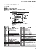
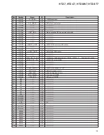
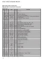
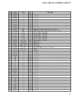
PDG250A (IC8501: MAIN ASSY)
System Micro-computer (for Subwoofer)
Pin Function


