background image

4

PRO-1000HD / PRO-800HD

Part Names and Functions

Main Unit

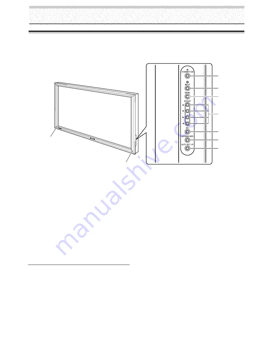
Main unit

1

STANDBY/ON indicator

This indicator is red during standby mode, and turns
to green when the unit is in the operation mode
(page 20).
Flashes green when Power-Management function is
operating (page 24).
The flashing pattern is also used to indicate error
messages (page 35).

2

Remote control sensor

Point the remote control toward the remote sensor to
operate the unit (page 6).

Operation panel on the main unit

3

STANDBY/ON button

Press to put the display in operation or standby mode
(page 20).

4

INPUT button

Press to select input (page 20).

5

MENU button

Press to open and close the on-screen menu (pages
18 to 32).

6

ADJUST (

5

/

/

3

/

2

) buttons

Use to navigate menu screens and to adjust various
settings on the unit.
Usage of cursor buttons within operations is clearly
indicated in the on-screen display (pages 18 to 32).

7

SET button

Press to adjust or enter various settings on the unit
(pages 18 to 32).

8

SCREEN SIZE button

Press to select the screen size (page 22).

9

AUTO SET UP button

When using computer signal input, automatically sets
the POSITION and CLOCK/PHASE to optimum values
(page 26).

Main unit

Operation panel on the main unit

2

1

3

4

5

6

7

8

9

Summary of Contents for Elite PRO-800HD

Page 1: ...Operating Instructions PLASMA DISPLAY PRO 1000HD PRO 800HD ...

Page 2: ...e found on labels attached to the product They alert the operators and service personnel of this equipment to any potentially dangerous conditions WARNING This symbol refers to a hazard or unsafe practice which can result in personal injury or property damage CAUTION This symbol refers to a hazard or unsafe practice which can result in severe personal injury or death i CAUTION WHEN POSITIONING THI...

Page 3: ... on an unstable cart stand tripod bracket or table The product may fall causing serious injury to a child or adult and serious damage to the product Use only with a cart stand tripod bracket or table recommended by the manufacturer or sold with the product Any mounting of the product should follow the manufacturer s instructions and should use a mounting accessory recommended by the manufacturer C...

Page 4: ...d operation Product Name Plasma Display with Video Card Model Number PRO 1000HD PRO 800HD Product Category Class B Personal Computers Peripherals Responsible Party Name PIONEER ELECTRONICS USA INC Customer Support Division Address P O BOX 1760 LONG BEACH CA 90801 1760 U S A Phone 800 421 1625 URL http www Pioneerelectronics com Pioneer Electronics USA Inc Customer Support Division P O BOX 1760 Lon...

Page 5: ...COLOR TEMP 29 Reducing Video Noise DIGITAL NR 29 Setting the PureCinema mode 30 Viewing a Fast Moving Picture 3D Y C MODE 30 Viewing in a Bright Location HIGH CONTRAST 31 Power Control Function 31 AUTO FUNCTION 32 Audio Output AUDIO OUT 32 Additional Information 33 Cleaning 33 Troubleshooting 33 Specifications 36 Supplement 1 37 Supplement 2 39 Supplement 3 39 Explanation of Terms 39 Thank you ver...

Page 6: ...e button or control is only present on the main unit However if a button or control on the main unit has the same or similar name as that on the remote control unit that button can be used when performing operations Note The screen displays depicted in this manual represent typical display examples The actual items and contents seen in screen displays may vary depending on input source and specifi...

Page 7: ...se familiarize yourself with this process before continuing on with the rest of this manual 1 Press MENU to display the menu screen MAIN MENU INPUT1 SELECT ENTER EXIT SET MENU PICTURE SCREEN SET UP OPTION 0 6 0 6 0 6 0 0 0 CONT RAST 0 BR R L EV EL I GHT G L EV EL B L EV EL H E NHANCE V E NHANCE R S ET E 2 Press 3 to select SCREEN SELECT ENTER EXIT SET MENU PICTURE SCREEN SET UP OPTION 0 0 POS I T ...

Page 8: ...put the display in operation or standby mode page 20 4 INPUT button Press to select input page 20 5 MENU button Press to open and close the on screen menu pages 18 to 32 6 ADJUST 5 3 2 buttons Use to navigate menu screens and to adjust various settings on the unit Usage of cursor buttons within operations is clearly indicated in the on screen display pages 18 to 32 7 SET button Press to adjust or ...

Page 9: ...o not use the remote control unit in a location subject to direct sunlight heat radiation from a heater or in a place subject to excessive humidity When the remote control unit s batteries begin to wear out the operable distance will gradually become shorter When this occurs replace all batteries with new ones as soon as possible Inserting the batteries in the remote control unit CAUTION Insert ba...

Page 10: ...of this unit is off or in standby mode page 11 7 INPUT2 BNC jacks For connection of components that have RGB or component output jacks such as a personal computer DVD player or external RGB decoder Make sure that the connection made corresponds to the format of the signal output from the connected component pages 9 to 12 If you are having difficulty with operation of the remote control unit The re...

Page 11: ...o deck video camera LaserDisc player or DVD player page 13 AUDIO INPUT4 RCA Pin jacks Use to obtain sound when INPUT4 is selected Connect these terminals to the audio output connectors of components connected to INPUT4 page 15 Note The left audio channel L jack is not compatible with monaural input sources INPUT4 BNC jack For connection of components that have a composite video output terminal suc...

Page 12: ...e shown in the diagram below Be sure to attach in 4 or more locations above and below left and right of the center line Use bolts that are long enough to be inserted 1 2 inch 12 mm to 11 16 inch 18 mm into the main unit from the attaching surface for both a holes and b holes Refer to the side view diagram below As this unit is constructed with glass be sure to install it on a flat unwarped surface...

Page 13: ... display pages 9 to 15 1 Although INPUT1 INPUT2 are compatible with various kinds of signals setup using the on screen menu is necessary after connections are made in order match the characteristics of the source component pages 18 and 19 2 INPUT1 is compatible with Microsoft s Plug Play VESA DDC 1 2B 3 Depending on the video output board of the computer this type of connection may not be possible...

Page 14: ...h output that has the vertical synchronization signal layered on top of the horizontal synchronization signal When connecting to INPUT1 On screen setup is necessary after connection Please see pages 18 and 19 When connecting to INPUT2 When using INPUT2 set the impedance selector switch to match the output impedance of the connected component s synchronization signal When the output impedance of th...

Page 15: ...nal When the output impedance of the computer s synchronization signal is below 75 Ω set this switch to the 75 Ω position On screen setup is necessary after connection Please see pages 18 and 19 When connecting to INPUT1 ANALOG RGB ANALOG RGB INPUT1 OUTPUT Connect the cable corresponding to the shape of the input terminal on this unit and the personal computer s output terminal Secure by tightenin...

Page 16: ...sonal computer with output that has the vertical synchronization signal layered on top of the horizontal synchronization signal When connecting to INPUT1 ANALOG RGB ANALOG RGB INPUT1 OUTPUT On screen setup is necessary after connection Please see pages 18 and 19 When connecting to INPUT2 G B R HD VD ON SYNC H V SYNC Ô 75 2 2 Ω kΩ INPUT2 When using INPUT2 set the impedance selector switch to match ...

Page 17: ...ode Connection to INPUT3 Connect an AV component that has S video output terminal to the S VIDEO input terminal AV component AV component To a monitor or a recording device About DTV Set Top Box Connection To ensure proper connection please carefully read the instruction manual supplied with the DTV set top box The set top box output signals that this display is compatible with are as follows S VI...

Page 18: ...together Push tab to the open position and insert the wire Then close tab firmly to secure the wire in place Audio connections for component computer connected to INPUT 1 or INPUT 2 VD Ô 75 2 2 Ω kΩ INPUT INPUT1 2 OUTPUT AUDIO Audio input to the AUDIO INPUT terminal stereo mini jack is possible for a component connected to either INPUT1 or INPUT2 Sound is output from both the AUDIO OUTPUT terminal...

Page 19: ...mote control operation of connected PIONEER components that bear the Î logo mark is done through the remote sensor on this unit When the connection is made to the CONTROL IN terminal on another unit the remote sensor of that component will no longer receive signals Point the remote control unit of the connected component at the remote control sensor on this unit to control Notes Make sure the powe...

Page 20: ...pply voltage other than that indicated AC 120 V 60 Hz as this may cause fire or electric shock For the plasma display a three core power cord with a ground terminal is used for efficiency protection Always be sure to connect the power cord to a three pronged grounded outlet and make sure that the cord is properly grounded If you use a power source converter plug use an outlet with a ground termina...

Page 21: ... designed to be difficult to undo once in place Please attach carefully To attach the speed clamps to the main unit Connect the speed clamps using the 4 holes marked with Black dot below depending on the situation To remove speed clamps Using pliers twist the clamp 90 and pull it outward In some cases the clamp may have deteriorated over time and may get damaged when removed 2 Bunch separated cabl...

Page 22: ...deo signal It is not supported when inputting a computer signal or when the Screen Mode setting has been used to select a mode other than VIDEO 1 Switch the main power switch on the connection panel to the on position to turn on the unit s main power The STANDBY ON indicator lights red 2 Press STANDBY ON to put the unit in the operation mode The STANDBY ON indicator turns green 3 Select INPUT1 or ...

Page 23: ...he signal output of the component that you are using For details please refer to the instruction manual supplied with the component you are connecting 9 Press SET repeatedly to select the input signal format Selection will change as follows each time SET is pressed RGB COMPONENT The table below shows what settings are appropriate and available for the type of connections made Set SETTING and VIDEO...

Page 24: ...l input will cause the menu screen to turn off If the input computer signal is not supported by the display the following message will be displayed 0 8 5 5 1 2 6 8 4 k H z f V 1 7 1 7 H z f H P O U SUP N S R ED T I NAL G CAU I O N T FUL L I NPUT 1 X 0 2 0 k H z f V 7 7 1 5 H z f H T OU N O A R F G E CAU I O N T FUL L I NPUT 1 4 Use VOLUME on the remote control unit to adjust the volume If no audio...

Page 25: ...tically canceled about 8 minutes after the button is pressed and the volume level is adjusted to the minimum level Press VOLUME or VOLUME to adjust the volume at a desired level To confirm display settings S VIDEO VIDEO DISPLAY Press DISPLAY on the remote control unit The currently selected input screen size and refresh rates will be displayed for about 3 seconds O D BY T DOT I NPUT 1 0 6 0 4 6 0 ...

Page 26: ... turned on in order to prevent image burning Moving the screen position upward or downward When a vista size movie etc is viewed at the ZOOM setting the image may not be centered on the screen and may extend past the edge of the screen In this case adjust the screen to an clearly viewable position using 5 Automatic screen size When a High Definition Television signal 1080i 720p 1080p is detected t...

Page 27: ...nlarged based on the screen center 5 2 3 can be used to move the enlarged portion up down and right left If no operation is undertaken for three seconds or more the display screen will disappear SET or 5 2 3 can be pressed again if desired to change the zoom ratio or display position 4 Press the remote control unit s POINT ZOOM once again to cancel the point zoom operation The point zoom function ...

Page 28: ...URE SCREEN SET UP OPTION AU T O S E T T I N CL AMP POWE R G OF F P S I T I ON O M NA GEME A I NP UT I NP UT 1 L E B L A V GA NT MAIN MENU INPUT1 In all other cases PICTURE SCREEN SET UP OPTION V GA AU T O S E T T I N CL AMP A UTO POWE R G OF F OF F P S I T I ON O I NP UT I NP UT 2 L E B L A MAIN MENU INPUT2 4 Press SET to confirm selection of the POWER MANAGEMENT or AUTO POWER OFF When OFF is sele...

Page 29: ... V ENHANCE Sharpens the image in the vertical direction 1 Press MENU to display the menu screen R S ET E SELECT ENTER EXIT SET MENU PICTURE SET UP OPTION 0 CONT RAST 0 BR I GHT 0 CO LOR 0 T I NT 0 SH ARP MAIN MENU INPUT1 When computer signal is input to INPUT 1 or 2 MAIN MENU INPUT1 SELECT ENTER EXIT SET MENU PICTURE SCREEN SET UP OPTION 0 6 0 6 0 6 0 0 0 CONT RAST 0 BR R L EV EL I GHT G L EV EL B...

Page 30: ...l is input The settings on this page are not supported when a signal is input from a connected video component Note Make these adjustments for each input INPUT1 to INPUT2 and signals SCREEN mode adjustment items Below are brief descriptions of the options that can be set in the SCREEN mode POSITION H POSITION Adjust the picture s position to the left or right V POSITION Adjust the picture s positi...

Page 31: ... to exit the menu screen Notes When CLOCK adjustment is carried out the H POSITION setting may have to be re adjusted If the adjustment items in the SCREEN mode are adjusted excessively the picture may not be displayed properly To reset SCREEN mode settings to the default If settings have been adjusted excessively or the picture on the screen no longer appears natural it may prove more beneficial ...

Page 32: ... L A T E S RE D N E A E C A S P MAIN MENU INPUT1 5 Press 2 3 5 to select the first desired character here C then press SET to confirm repeat this step to input up to eight desired characters SELECT SET EXIT SET MENU BACK SPACE J M K L B C D E F G H W Z X Y N O P Q R S T V U 9 0 1 2 3 4 5 6 8 7 I NP UT I NP UT 1 L E B L A T E S RE E C A S P D N E A C I MAIN MENU INPUT1 Usable characters include 52 ...

Page 33: ...nce again to return to the normal display 3 MIDDLE MID LOW 2 LOW 2 3 MID HIGH 3 HIGH Reducing Video Noise DIGITAL NR Make this setting if video noise is objectionable Note Digital noise reduction settings are supported only with input signals from a video device Settings are made individually for each of the inputs INPUT1 INPUT4 1 Press MENU to display the menu screen R S ET E SELECT ENTER EXIT SE...

Page 34: ... P P OWER G OF F P S I T I ON O D I G I T AL NR OF F H I GH CO T N RA T S OF F L OW COL OR T M E P M I DDL E MAIN MENU INPUT1 P URE I C N MA E I NP UT 1 4 Press SET to select the desired PureCinema mode Each time SET is pressed the screen mode setting changes as shown 5 Following completion of the setting press MENU once again to return to the normal display Viewing a Fast Moving Picture 3D Y C MO...

Page 35: ...D H I GH CO T N RA T S OF F L OW COL OR T M E P M I DDL E MAIN MENU INPUT4 I NP UT 4 P URE I C N MA E 4 Press SET to set the mode to ON OFF is set when this unit is shipped from the factory Each time SET is pressed the settings change in the following order 5 When the setup is finished press MENU to exit the menu screen 3 ON OFF 2 Power Control Function The power control function allows screen bri...

Page 36: ...ll automatically switch back to the original input source used before the AUTO FUNCTION facility was enabled 5 Following completion of settings press MENU again to return the display to its normal screen Note The AUTO FUNCTION for INPUT1 is supported only when a separate SYNC or composite SYNC analog RGB signal is input When a G on SYNC or component video signal is input AUTO FUNCTION is disable 3...

Page 37: ...em to be a malfunction may be remedied with a quick check Please check to see if a warning is displayed on the screen If displayed refer to the table below and check the mode If there is no display check to see if the problem is listed on page 34 The problem may also be caused by something other than this unit so please also check the other components being used such as a video deck If the problem...

Page 38: ...ges 9 37 and 38 Is picture adjustment correct page 25 The screen is displayed in a small size Letter breakup on screen A sharp sound is sometimes heard from the cabinet Bright portions of image appear to be losing intensity Speckles or noise appears on screen Stripes appear on the screen Sound is heard from inside the unit Fan isn t moving Fan speed changes Check the input signal compatibility cha...

Page 39: ...and respond accordingly pages 34 35 If the problem persists disconnect the power plug and consult your dealer or a service center When STANDBY ON is pressed to set the unit to the standby mode the indicator will flash red for several seconds page 20 Other than this if the power turns off by itself or refuses to turn on or if the red indicator conditions flashing a malfunction may be indicated Imme...

Page 40: ...with buffer INPUT 2 Input BNC jack x5 1 RGB signal G ON SYNC compatible RGB 0 7 Vp p 75 Ω no sync HD CS VD TTL level positive and negative polarity 75 Ω or 2 2 kΩ impedance switch G ON SYNC 1 Vp p 75 Ω negative sync Additional Information 2 Component video signal Y 1 Vp p 75 Ω negative sync CB PB CR PR 0 525 Vp p 75 Ω 75 satulation level INPUT 3 Input S terminal Mini DIN 4 pin Y C saparate video s...

Page 41: ...Hz 31 5kHz 31 5kHz 35 0kHz 37 9kHz 37 5kHz 43 3kHz 35 2kHz 37 9kHz 48 1kHz 46 9kHz 53 7kHz 49 7kHz 31 7kHz 48 4kHz 56 5kHz 60 0kHz 60 2kHz 68 7kHz 45 1kHz 48 4kHz 56 1kHz 1024x768 1024x768 1024x768 640x480 800x600 832x624 852x480 1024x768 1280x768 4 3 NEC PC 9800 NEC PC 9800 852x480 864x480 Apple Macintosh 13 1072x600 Apple Macintosh 16 1376x768 indicates Apple Macintosh 19 Not available Optimal p...

Page 42: ...60 2kHz 68 7kHz 45 1kHz 48 4kHz 56 1kHz 768x768 768x768 768x768 768x768 640x480 800x600 832x624 852x480 1024x768 4 3 NEC PC 9800 NEC PC 9800 852x480 864x480 Apple Macintosh 13 1072x600 Apple Macintosh 16 1376x768 indicates Apple Macintosh 19 Not available PC signal compatibilty table INPUT1 INPUT2 Refresh rate 2 2 PRO 800HD Input signal and screen s dot x line ratio are made to display at 1 1 rati...

Page 43: ... video signal format composed of the Y CB CR Y PB PR and Y B Y R Y luminance signal color signal The component video signal is sometimes simply called the color difference signal G ON SYNC This indicates a video signal in the form of a synchronization signal added to the G GREEN signal of the R G B signal VGA VGA is short for Video Graphics Array Generally this indicates a 640 dot x 480 line resol...

Page 44: ...served TSZZF 02E00000 Printed in USA ARB1548 A PIONEER CORPORATION 4 1 Meguro 1 Chome Meguro ku Tokyo 153 8654 Japan PIONEER ELECTRONICS USA INC P O BOX 1540 Long Beach California 90801 1540 U S A PIONEER ELECTRONICS OF CANADA INC 300 Allstate Parkway Markham Ontario L3R OP2 Canada ...

Reviews: