DVR-220-S
64
1
2
3
4
1
2
3
4
C
D
F
A
B
E
6. ADJUSTMENT
6.1 TUNB ASSY ADJUSTMENT
Audio ouput (L)
(Rear panel)
Audio ouputs (L/R)
(Rear panel)
Audio ouputs (L/R)
(Rear panel)
Best point of separation
≥
25dB Note 1
Best point of separation
≥
30dB Note 1
2
370mVrms
±
18.5mV
3
Input a signal of Mono 1kHz/100% modulation
to terrestrial tuner input. /through output.
Input a signal of Stereo 300Hz/30% modulation
(NR-ON/L ch only) to terrestrial tuner input.
Note 2
Input a signal of Stereo 3kHz/30% modulation
(NR-ON) to terrestrial wave input. /through output
Note 2
Note 1 : The values for channel separation is defined as those having passed through the following filters :
100Hz – 10kHz : +0/–0.5dB
15.75kHz – 100kHz : -40dB or more
Note 2 : The adjustment No.2 and No.3 should be repeated 2 times for good adjustment.
(Steps : No.1
→
No.2
→
No.3
→
No.2
→
No.3)
No.
Adjustment Name
Adj. Point Measurement Point
Adjustment Value
Adjustment State
1
Stereo Decoder ATT adjustment
(Input system adjustment)
Stereo Decoder Wideband
adjustment (Input system adjustment)
Stereo Decoder Spectral adjustment
(Input system adjustment).
VR453
VR451
VR452
5
4
3
2
1
19
1
13
1
R328
R325
R324
C328
L306
C327
KN300
C329
D301
U301
C326
Q301
R301
C304
C301
C302
R307
R306
C313
D302
C303
C309
Q302
C305
C306
R312
R315
C319
R316
R317
R318
Q304
L303
JA301
C316
Q306
C318
CN301
C461
C451
VR451
VR452
R454
R453
R455
C459
C453
C462
C456
C458
C460
R463
VR453
C465
R467
R466
R468
C473
Q451
CN451
C467
C468
C471
C472
C474
R471
R326
VNP1963-A
LF
SEPA
WIDE
INPUT
LAVEL
ADJAST
SPECTRUM
SEPA
ADJAST
ADJAST
FC
ICT
V+9
V+9
GND
V+5TU
VWV
or
GND
PC
G-Link
TUNB
PYKC F4X
C2
B
E
E2
B2
C
R
NP
19
1
NP
13
1
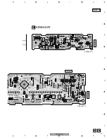
TUNB ASSY
A
SIDE A
VR451
VR452
VR453
Fig.1 Adjustment Points (TUNB ASSY)
*
It is not necessary to adjust the ASSY normaly when exchanging the ASSY. But the adjustment is
necessary when exchanging the Tuner Module and IC451 stereo decoder IC.


