29
DV-210K-K
5
6
7
8
5
6
7
8
A
B
C
D
E
F
7. DISASSEMBLY
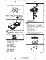
1-1:
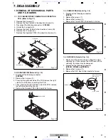
1. REMOVAL OF MECHANICAL PARTS
AND P.C. BOARDS
Remove the 5 screws (1).
Remove the Top Cabinet in the direction of arrow (A).
Disconnect the following connectors:
(CP4002)
.
Unlock the 4 supports (2).
Remove the Front Cabinet in the direction of arrow (B).
Remove the 11 screws (3).
Remove the Operation PCB in the direction of arrow (C).
TOP CABINET/FRONT CABINET AND OPERATION
PCB (Refer to Fi
g
. 1-1)
1.
2.
3.
4.
5.
6.
7.
1.
2.
3.
4.
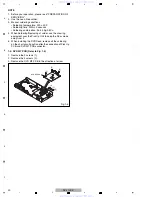
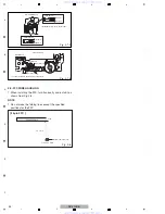
Short circuit the position shown in
Fi
g
. 1-4
using a
soldering iron. If you remove the D
V
D Deck with no
soldering, the Laser may be damaged.
Disconnect the following connectors:
(CP2301, CP2302 and CP2303)
.
Remove the 4 screws (1).
Remove the D
V
D Deck in the direction of arrow.
1-4: DVD DECK (Refer to Fi
g
. 1-4)
Fig. 1-4
D
V
D Deck
Short circuit using a
soldering iron.
Pick Up PCB
(1)
(1)
(1)
(1)
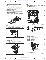
1-2: KARAOKE PCB (Refer to Fi
g
. 1-2)
1-3: POWER PCB (Refer to Fi
g
. 1-3)
1.
2.
3.
4.
Disconnect the following connectors:
(CP502)
.
Remove the screws (1).
Remove the 3 screws (2).
Remove the Power PCB in the direction of arrow.
Fig. 1-3
Power PCB
(2)
(2)
(2)
(1)
Fig. 1-2
Karaoke PCB
Fig. 1-1
(B)
(A)
Top Cabinet
Front Cabinet
(C)
Operation PCB
Operation PCB
(C)
(1)
(1)
(1)
(1)
(1)
(2)
(2)
(2)
(2)
(3)
(3)
(3)
(3)
(3)
(3)
(3)
(3)
1.
2.
5.
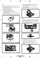
Disconnect the following connector:
(CP
8
003)
Remove the 2 screws (1).
3. Pressing the right back side of the PCB, remove the right
side hook of the chassis catching the PCB.
4. Then, pressing the left side back side of the PCB, remove
the left side hook of the chassis.
Remove the Karaoke PCB in the direction of arrow.
www. xiaoyu163. com
QQ 376315150
9
9
2
8
9
4
2
9
8
TEL 13942296513
9
9
2
8
9
4
2
9
8
0
5
1
5
1
3
6
7
3
Q
Q
TEL 13942296513 QQ 376315150 892498299
TEL 13942296513 QQ 376315150 892498299

