background image

17

En

En
g

lis

h

Front speaker
Rear speaker
White
White/black
Gray
Gray/black
Green
Green/black
Violet
Violet/black
Black (chassis ground)
Connect to a clean, paint-free metal 
location.
Yellow
Connect to the constant 12 V supply 
terminal.
Red
Connect to terminal controlled by the 
ignition switch (12 V DC).
Blue/white
Connect to the system control terminal 
of the power amp or auto-antenna relay 
control terminal (max. 300 mA 12 V DC).
Subwoofer (4 Ω)
When using a subwoofer of 70 W (2 Ω), 
be sure to connect the subwoofer to the 
violet and violet/black leads of this unit. 
Do not connect anything to the green 
and green/black leads.
Not used.
Subwoofer (4 Ω) × 2
Orange/white
Connect to a car’s illumination signal.
Yellow/black (Only for FH-X579UI)
If you use equipment with a Mute 
function, wire this lead to the Audio 
Mute lead on that equipment. If not, 
keep the Audio Mute lead free of any 
connections.

NOTE

Change the initial menu of this unit. Refer 
to [SP-P/O MODE] (page 6). The subwoofer 
output of this unit is monaural.

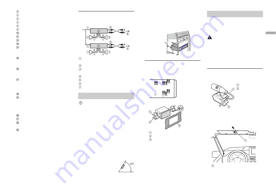
Power amp (sold separately)

Perform these connections when using the 
optional amplifier.

System remote control
Connect to blue/white cable.

Power amp (sold separately)
Connect with RCA cables (sold 

separately)

To front output
Front speaker
To rear output or subwoofer output
Rear speaker or subwoofer

 Important

Check all connections and systems before 
final installation.

Do not use unauthorized parts as this 
may cause malfunctions.

Consult your dealer if installation requires 
drilling of holes or other modifications to 
the vehicle.

Do not install this unit where:
– it may interfere with operation of the 

vehicle.

– it may cause injury to a passenger as a 

result of a sudden stop.

The semiconductor laser will be damaged 
if it overheats. Install this unit away from 
hot places such as near the heater outlet.

Optimum performance is 
obtained when the unit is 
installed at an angle of less 
than 60°.

Installation

When installing, to ensure proper heat 
dispersal when using this unit, make sure 
you leave ample space behind the rear 
panel and wrap any loose cables so they 
are not blocking the vents.

DIN Rear-mount

1

Determine the appropriate position 
where the holes on the bracket and 
the side of the unit match.

2

Tighten the screws on each side.

Truss screw (5 mm × 8 mm)
Mounting bracket
Dashboard or console

(Only for FH-X779BT)
The microphone should be placed directly 
in front of the driver at a suitable distance 
to pick up their voice clearly.

 CAUTION

It is extremely dangerous to allow the 
microphone lead to become wound 
around the steering column or shift lever. 
Be sure to install the microphone in such a 
way that it will not obstruct driving. It is 
recommended to use the clamps (sold 
separately) to arrange the lead.

To install on the sun visor

1

Fit the microphone lead into the 
groove.

2

Install the microphone clip on the sun 
visor.

Lowering the sun visor reduces the 
voice recognition rate.

Leave ample 
space

5 cm

5 cm

Installing the microphone

Microphone lead
Groove

Microphone clip

Summary of Contents for DEH-X4790BT

Page 1: ...English CD RDS RECEIVER FH X779BT FH X579UI Owner s Manual ...

Page 2: ...12 AUDIO settings 13 SYSTEM settings 13 ILLUMINATION settings 14 MIXTRAX settings 15 Connections Installation 16 Additional Information 19 Table of Contents About this manual In the following instructions a USB memory or USB audio player are referred to as USB device In this manual iPod and iPhone are referred to as iPod ...

Page 3: ...t attempt to operate the unit while driving Make sure to pull off the road and park your vehicle in a safe location before attempting to use the controls on the device CAUTION Do not allow this unit to come into contact with moisture and or liquids Electrical shock could result Also damage to this unit smoke and overheating could result from contact with liquids Always keep the volume low enough t...

Page 4: ... Turn the M C dial Press VOLUME or Press MUTE to mute the unit Press again to unmute Select a source Press SRC OFF repeatedly Press SRC repeatedly Change the display information Press DISP repeatedly Press DISP repeatedly Return to the previous display list Press DIMMER Press to select the next previous folder Return to the normal display from the menu Press BAND Answering a call Press Press Endin...

Page 5: ...et at this time turn the M C dial to select NO then press to confirm 2 Turn the M C dial to select the options then press to confirm To proceed to the next menu option you need to confirm your selection 3 QUIT YES appears when all the settings have been made To return to the first item of the setup menu turn the M C dial to select QUIT NO then press to confirm 4 Press the M C dial to confirm the s...

Page 6: ...d hold one of the number buttons 1 to 6 until it stops flashing The unit searches for a station by PTY program type information 1 Press during FM reception INITIAL settings Menu Item Description FM STEP Select the FM tuning step from 100 kHz or 50 kHz 100 50 MW STEP Select the MW tuning step from 10 kHz or 9 kHz 10 9 SP P O MODE Select when there is a full range speaker connected to the rear speak...

Page 7: ...evice as any device connected directly to the unit will protrude out from the unit which could be dangerous Before removing the device stop playback MTP connection A device installed with Android OS 4 0 or later can be connected to the unit via MTP using the cable supplied with the device However depending on the connected device and the numbers of the files in the device audio files songs may not...

Page 8: ...re still accessible from the unit even if the control mode is set to CONTROL iPod Pause fast forward reverse song chapter selection The volume can only be adjusted from the unit Search for a file from a list 1 Press to display the list 2 Turn the M C dial to select the desired file folder name or category then press to confirm 3 Turn the M C dial to select the desired file then press to confirm Pl...

Page 9: ...s In this case delete one of the paired devices See DEL DEVICE or GUEST MODE in the connection menu page 9 Depending on the device the PIN code is required in step 6 In this case input 0000 TIP The Bluetooth connection can be also made by detecting the unit from the Bluetooth device To do so VISIBLE in the connection menu needs to be set to ON For details on a Bluetooth device operations refer to ...

Page 10: ...all using a preset number press one of the number buttons 1 to 6 then press the M C dial Voice recognition Only for iPhone This function is only available when an iPhone equipped with voice recognition is connected to the unit via Bluetooth 1 Press and hold the M C dial to activate the voice recognition mode 2 Press the M C dial and then talk into the microphone to input voice commands To exit the...

Page 11: ...r certain applications the provision of geolocation data ALL THIRD PARTY APPS ARE THE SOLE RESPONSIBILITY OF THE PROVIDERS INCLUDING WITHOUT LIMITATION COLLECTION AND SECURITY OF USER DATA AND PRIVACY PRACTICES BY ACCESSING THIRD PARTY APPS YOU AGREE TO REVIEW THE TERMS OF SERVICE AND PRIVACY POLICIES OF THE PROVIDERS IF YOU DO NOT AGREE WITH THE TERMS OR POLICIES OF ANY PROVIDER OR DO NOT CONSENT...

Page 12: ...ording to the source Purpose Operation Select a track Press or Fast forward or reverse Press and hold or Pause resume playback Press BAND Settings FUNCTION settings Menu Item Description BSM Store the six strongest stations on the number buttons 1 to 6 automatically REGIONAL ON OFF Limit the reception to the specific regional programs when AF alternative frequencies search is selected Available on...

Page 13: ...Z 250HZ 800HZ 2 5KHZ 8KHZ Equalizer level 6 to 6 Select or customize the equalizer curve CUSTOM1 can be set separately for each source However each of the below combinations are set to the same setting automatically USB iPod and APP iPhone BT AUDIO and APP Android CUSTOM2 is a shared setting used for all sources LOUDNESS OFF LOW MID HI Compensate for clear sound at low volume Menu Item Description...

Page 14: ...cording to your wired remote control Menu Item Description ILLUMINATION settings Menu Item Description COLOR KEY COLOR DISP COLOR BOTH COLOR Select color for the keys display of the unit from 12 preset colors SCAN or CUSTOM SCAN Cycle through a variety of colors automatically CUSTOM 1 Press and hold the M C dial until the color setting display appears 2 Set the primary color R red G green B blue a...

Page 15: ...gs page 14 is used as the display color FLASH PATTERN SOUND LEVEL 1 to SOUND LEVEL 6 Change the illumination effect according to the sound and bass level The flash pattern changes according to the sound level LOW PASS 1 to LOW PASS 6 The flash pattern changes according to the bass level RANDOM1 The flash pattern changes randomly according to the sound level mode and low pass mode RANDOM2 The flash...

Page 16: ... any disconnected cable connectors with insulating tape Do not shorten any cables Never cut the insulation of the power cable of this unit in order to share the power with other devices The current capacity of the cable is limited Use a fuse of the rating prescribed Never wire the negative speaker cable directly to ground Never band together negative cables of multiple speakers When this unit is o...

Page 17: ... parts as this may cause malfunctions Consult your dealer if installation requires drilling of holes or other modifications to the vehicle Do not install this unit where it may interfere with operation of the vehicle it may cause injury to a passenger as a result of a sudden stop The semiconductor laser will be damaged if it overheats Install this unit away from hot places such as near the heater ...

Page 18: ...l on the steering column 1 Slide the microphone base to detach it from the microphone clip Microphone Microphone clip Microphone base 2 Install the microphone on the rear side of the steering column Double sided tape ...

Page 19: ... Replace the disc ERROR 23 Unsupported CD format Additional Information Troubleshooting Error messages Replace the disc FORMAT READ Sometimes there is a delay between the start of playback and when you start to hear any sound Wait until the message disappears and you hear sound NO AUDIO The inserted disc does not contain any playable files Replace the disc SKIPPED The inserted disc contains DRM pr...

Page 20: ... and ejecting may not be possible Using such discs may result in damage to this equipment Do not attach commercially available labels or other materials to the discs The discs may warp making the disc unplayable The labels may come off during playback and prevent ejection of the discs which may result in damage to the equipment USB storage device Connections via USB hubs are not supported Firmly s...

Page 21: ...ompatible Partitioned USB device Only the first partition can be played iPod compatibility Audiobook Podcast Compatible CAUTION Pioneer accepts no responsibility for data lost on the iPod even if that data is lost while this unit is used The user cannot assign folder numbers and specify playback sequences with this unit Sequence of audio file depends on the connected device Note that the hidden fi...

Page 22: ... audio Windows Media Player WAV signal format Linear PCM MS ADPCM Non compressed FM tuner Frequency range 87 5 MHz to 108 0MHz Usable sensitivity 11 dBf 0 8 μV 75 Ω mono S N 30 dB Signal to noise ratio 72 dB IEC A network MW tuner Frequency range 531 kHz to 1 602 kHz 9 kHz 530 kHz to 1 640 kHz 10 kHz Usable sensitivity 25 μV S N 20 dB Signal to noise ratio 62 dB IEC A network SW tuner Frequency ra...

Page 23: ...23 En English ...

Page 24: ... 2014 PIONEER CORPORATION All rights reserved QRB3493 A ID ...

Reviews: