background image

44

DDJ-RB

1

2

3

4

A

B

C

D

E

F

1

2

3

4

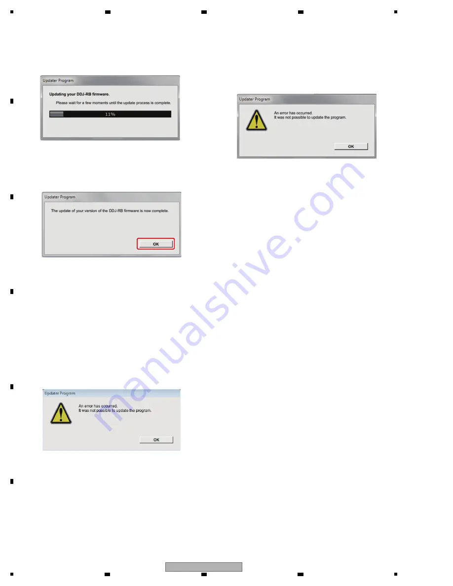
Update screen during updating
Please wait until the progress bar on the screen reaches 
100%. 

Corrective actions to be taken when "Your DDJ-RB is 
not connected" is displayed:

If "Your DDJ-RB is not connected" is displayed after 
selection of the language, check the following:

· Is the USB cable connected to the computer?

If it is not, connect the cable to the computer then perform 
the updating procedure again.

· If the above-mentioned message is displayed even if the

USB cable is connected to the computer, perform the
updating procedure indicated below.

1

 Uninstall the DDJ-RB driver software.

[How to uninstall the DDJ-RB driver software]

With Windows OS:

Click on Start, Control Panel, Programs, Programs and 
Functions, Pioneer DDJ-RB Driver, then Uninstall.
 

With Mac OS:

Double-click on the driver-software icon then double-click 
on "DDJ-RB Uninstaller.app."
Follow the instructions displayed on the screen of the PC.

Visit the Website indicated below to download the latest 
version of the driver software:
http://pioneerdj.com/support/index.php?lang=ja

2

 Update the firmware again.

3

 After updating of the firmware is completed, install the 

driver software again.
For details on how to install the driver software, refer to 
the operating instructions of the DDJ-RB.

[Reference Information]

You can run this updater program only on the following OS:  

Windows: Windows 10/ Windows 8.1 /

 Windows 7

MacOS: OS X 10.11/ 10.10/ 10.9

It will take approximately 1 minutes to complete the update 
process.

 
The screen displays shown in this manual are under 
development and are subject to change.

<STEP4> Update screen when the update is completed 

Make sure that the update process has been 
completed. 
When the following “Update completed” message 
appears, click [OK].

<STEP5> Restart DDJ-RB. 

Please turn off the power of DDJ-RB and then 
turn it on again.

E. Check the current version.

Check the firmware version of DDJ-RB in the same procedure 
with "A. Check the current DDJ-RB version.".
Update is completion if you consist in the version that a 
firmware version wants to update.

If updating failed:

If the error message shown below is displayed during 
updating, disconnect the USB cable then proceed with the 
steps from the beginning.

Summary of Contents for DDJ-RB

Page 1: ...WING MODEL S AND TYPE S THIS SERVICE MANUAL SHOULD BE USED TOGETHER WITH THE FOLLOWING MANUAL S Model Type Power Requirement Remarks DDJ RB SXJ DC 5 V USB bus power only DDJ RB XJCN DC 5 V USB bus power only Model Order No Remarks DDJ RB RRV4651 SCHEMATIC DIAGRAM PCB CONNECTION DIAGRAM PCB PARTS LIST K ZZZ APR ...

Page 2: ...it is not meant for the casual do it yourselfer Qualified technicians have the necessary test equipment and tools and have been trained to properly and safely repair complex products such as those covered by this manual Improperly performed repairs can adversely affect the safety and reliability of the product and may void the warranty If you are not qualified to perform the repair of this product...

Page 3: ...N DIAGRAM 7 4 2 OVERALL BLOCK DIAGRAM 8 4 3 POWER BLOCK DIAGRAM 9 5 DIAGNOSIS 10 5 1 POWER ON SEQUENCE 10 5 2 TROUBLESHOOTING 11 5 3 MONITORING OF POWER SUPPLY AND VOLTAGE 18 5 4 ABOUT POWER SAVING MODE 19 5 5 OPERATION CHECK WITH rekordbox 20 6 SERVICE MODE 23 6 1 TEST MODE 23 7 DISASSEMBLY 35 8 EACH SETTING AND ADJUSTMENT 42 8 1 NECESSARY ITEMS TO BE NOTED 42 8 2 UPDATING OF THE FIRMWARE 43 8 3 ...

Page 4: ...nd PC1202 DCK1B ASSY DCK2B ASSY After replacement be sure to perform the procedure described in 2 2 Judging the quality of mounting and connection of the photointerrupter in 6 SERVICE MODE Mass production early the following parts IC711 IC712 MAIN Assy may have temporarily implement an alternate parts If it was alternate parts when replacing the following parts please replace in pairs to the corre...

Page 5: ...tructions Quick Start Guide License key card for rekordbox dj DXA2304 Accessories Distortion Noise Volume too low Volume too high Volume fluctuating Sound interrupted See the table below for the items to be checked regarding audio No Procedures Item to be checked regarding audio Check points 1 Check the firmware version The firmware version must be the latest one If it is not the latest one be sur...

Page 6: ...of use Remarks USB cable GGP1193 for PC connection Grease GEM1100 See 7 DISASSEMBLY 1 MAIN ASSY DWX3907 NSP 1 DCK1 ASSY DWM2625 2 DCK1B ASSY DWX3908 2 HPJK ASSY DWX3912 NSP 1 DCK2 ASSY DWM2626 2 DCK2B ASSY DWX3910 1 MXR ASSY DWX3911 Mark No Description Part No LIST OF ASSEMBLIES Bottom view HPJK ASSY B DCK1B ASSY C DCK2B ASSY D MXR ASSY E MAIN ASSY A ...

Page 7: ...AT_L 26 GND_D 27 LED_ON 28 LED_13 29 GRID_3 30 LED_12 31 GRID_2 32 LED_11 33 GRID_1 34 LED_10 35 GRID_0 36 LED_9 37 GND_LED 38 GND_LED 39 V 5_LED VKN2097 A CN1001 1 V 3R3_AD 2 AD_TEMPO_0 3 AD_FXLV 4 AD_TEMPO_1 5 GND_AD 6 GND_D 7 GND_D 8 JOG_TCH 9 FX_BEAT_R 10 V 3R3_D 11 FX_BEAT_L 12 JOG_DIAL_0 13 FX_ON 14 JOG_DIAL_1 15 GND_D 16 KEY_0 17 GND_D 18 KEY_1 19 GND_D 20 KEY_2 21 GND_D 22 KEY_3 23 LED_BEA...

Page 8: ...6 I P Touch uCom RPI 579N1 PHOTO INTERRUPTER RPI 579N1 PHOTO INTERRUPTER JOG_DIAL2_0 JOG_TCH2 1 1 JOG Touch JOG_DIAL2_1 IRQ LED LED Tr Buf Tr Buf 5 4 5 KEY GPIO GPIO GPIO GPIO 5 5 GPIO Tr Buf Tr Buf KEY No Mount FX1 LEVEL 7 7 1 GPIO 3 MUTE MUTE MUTE MASTER OUT RCA PIN Mute drive TC74VHC08FK HPAMP_BIAS FLASH_I2S_SEL FLASH_CS_EN GPIO DISCHARGE CIRCUIT XIN XOUT GPIO 1 1 1 1 MUX_SW_A MUX_SW_B MUX_SW_C...

Page 9: ...BUS VOLTAGE DETECTION CIRCUIT V 3R3_D OVER V 7 UNDER V 6 UNDER V 5_A UNDER OVER V 5_HP UNDER OVER FAULT_DET V 1R25_PLL L402 L404 MULTI PLEXER IC711 IC712 IC713 V 3R3_AD V 5_D SBD D210 P101 I2S BUFFER IC407 PWR_ON2 INVERTER IC410 R572 R571 V VBUS L406 MUTE Q705 Q706 HP_MUTE_DD A_MUTE_DD MUTE Q707 Q708 REGULATOR L OTHER FILTER COIL BEADS P ICP DC DC CONVERTER IC PROTECTOR R RESISTOR V 5_D V 3R3_SHD ...

Page 10: ...he load of JOG dial Photo interrupter check mode Peripheral device power ON Loading the program from FLASH to RAM Start up Start up of each task Initial settings of related port Related register RAM returns to a default Generation of tasks Start up In the order of start up To normal main loop processing Update mode Operation mode judgment Start up of real time OS Oscillation of peripheral module c...

Page 11: ... may be poor 4 3 POWER BLOCK DIAGRAM In a case where the unit is not started after the USB cable is connected and the unit is turned ON all LED are not lit 4 Power failure in the UCOM MAIN Assy If the V 3R3_SH voltage is normal check that Q203 5V FET SW is functioning properly If the PWR_ON signal is L V 5D V 5_LED will not be output because Q203 is not turned ON The error detection circuit may ha...

Page 12: ... AND VOLTAGE 1 Power failure in the UCOM MAIN Assy Check the power terminal of the UCOM IC406 Check the power and voltage are normal Check the power line and the parts such as coils beads resistors and capacitors If no problem was found with the parts power line and conduction between the power supply and GND the UCOM IC406 may be defective 10 13 WAVEFORMS PQR 2 UCOM Reset circuit error MAIN Assy ...

Page 13: ... line for the corresponding switch may be defective If other switches do not operate either a transistor in the switching detection section or its peripheral circuits may be defective 10 13 WAVEFORMS SWX 2 Defective UCOM IC406 MAIN Assy If the symptom persists after the above corrections The UCOM IC406 may be defective 7 Basic Operation Check of the UCOM 2 Defective UCOM IC406 MAIN Assy If the sym...

Page 14: ...s DCK1 Assy DCK2 Assy Check connections between IC1201 and UCOM IC406 If the connection is properly made the UCOM IC406 may be defective 5 Loose connection defective parts DCK1 Assy DCK2 Assy Check the signal of Pin 3 of IC1201 Test land Freq The signal produces a pulse waveform in the frequency range of 900 to 1300 kHz while the jog dial is not touched and a pulse waveform in the frequency range ...

Page 15: ...or UCOM IC406 is defective 0 Wrong input setting of the application installed on the PC Input setting of the application installed on the PC Check that the input setting of the application installed on the PC is appropriate The PC will not recognize the unit if the input setting of the application installed on the PC is inappropriate Operating instructions 1 MAIN Assy Check that an audio signal is...

Page 16: ...ut signal using pins 1 and 7 of the HP AMP IC706 If the output signal is normal connection of the audio signal between HP AMP IC706 and JH101 may be loose If the input signal is abnormal connection of the audio input signal line may be loose or the resistor or capacitor may be defective If the input signal is normal but the output signal is abnormal go to 4 2 MAIN Assy Check the audio output signa...

Page 17: ...tor for key detection If the waveform is abnormal connection of the KEY detection signal line may be loose or the switch transistor or diode may be defective 10 13 WAVEFORMS SWX 6 DCK1 Assy DCK2 Assy MXR Assy MAIN Assy When pressing the abnormal button check the KEY detection signal KEY_0 to KEY_11 corresponding to the abnormal key between the transistor for key detection and the UCOM If the wavef...

Page 18: ...ormal voltage continues the defective point may produce heat which may be dangerous Therefore during diagnosis be sure to disconnect the USB cable several seconds after they are connected so that forcible powering will not continue 5 If the voltage of any power IC is abnormal the circuit that uses that power or the power IC itself may be defective 6 Repair the defective part then check that the po...

Page 19: ...f MAIN Assy or IC713 MUX IC pin 13 V_DET_AD input terminal Normal Approximately 2 3 V to 2 6 V Abnormal 2 3 V Microcomputer Detection terminal and its terminal voltage 500 ms after the unit is turned ON Timing of monitoring start 50 msec after an error is detected Timing upon judgment as a failure V VBUS 4 2 4 5 V The maximum output level of the headphone is suppressed to approximately 15 If norma...

Page 20: ... performance function of rekordbox For the latest information on the required operating environment and compatibility as well as to acquire the latest operating system see Software Info of DDJ RB on the Pioneer DJ site and System Requirements of rekordbox com below http pioneerdj com support http rekordbox com Use the latest version service pack of the operating system Operating procedures 1 Conne...

Page 21: ... rekordbox dj Follow the instruction screens to activate rekordbox dj by entering the license key which is shown on the supplied license key card for rekordbox dj For the procedure to activate rekordbox dj access rekordbox com and read the rekordbox Manuals on the Support page http rekordbox com Installing the driver software 1 On the Audio Driver Install screen select DDJ RB from the pull down me...

Page 22: ... to select an audio track from Collection and then press the LOAD button on Deck 1 left The selected track is loaded Playing a track This section explains how to output sound from Deck 1 left as an example 1 Set the positions of the controls etc as shown below Names of controls etc Position TRIM Turned fully counterclockwise control EQ HI MID LOW Center position controls FILTER control Center posi...

Page 23: ...splay mode 1 5 Voltage value fluctuation range check mode 2 Test Mode 2 2 1 Measurement mode of the load of JOG dial 2 2 Photo interrupter check mode Power is OFF Press the SHIFT button right DECK Press the SHIFT button on the left DECK to go backward to the previous page Press the SHIFT button on the left DECK to go backward to the previous page Press the SHIFT button right DECK Press the SHIFT b...

Page 24: ...is to check the version of the firmware The version is displayed using the deck LEDs following red yellow and blue frame border colors in triple digit decimal number When you press the SHIFT button to enter the new test page the LED corresponding to each page will blink red for a moment for 1 to 2 seconds After the red blinking is over and the light is off the testing of each page will start 1 1 1...

Page 25: ...Brows Press Press Press Press Rotate Rotate Rotate Slide Rotate Slide Basic rule Except for TYPE B the number of lighting LEDs will change based on the position of each control fader i e when the volume is minimum no LED will light up when the volume is maximum all LEDs will light up TYPE C 3 TYPE B 2 TYPE A 1 PLAY CUE Own LED All LEDs light up all LEDs dimmer out Light off TYPE D 4 SHIFT Left Rig...

Page 26: ...g 8 LEDs The position of the of the knob fader will be displayed using the following 5 LEDs for each CH according to the move The LEDs will light up according to the position of the knob fader right after each knob is rotated fader is moved The position of the knob fader will be displayed using the following LEDs for both CHs according to the move The LEDs will light up according to the position o...

Page 27: ...PADs on the both DECKs will light in red When the reset failed the SYNC buttons will flash Setting Item Default Value 1 MIDI MODE AUTO 1 Factory default Genaral DJ App 2 Master output Mono Stereo switching Mono Stereo Factory default 3 4 Mic output Peak limiter Disable Enable Factory default 5 DEMO MODE OFF 1 min after no operation 5 min after no operation 10 min after no operation Factory default...

Page 28: ... the figure above The LED with a number colored white corresponds to the control having the same number 3 After the control to be tested is selected press the rotary selector to start monitoring the A D conversion values The reference value is the A D conversion value monitored immediately after the monitoring started The A D conversion values being monitored are raw data 4 The A D conversion valu...

Page 29: ... C D E F xxxx xxxx xxxx xxxx Display of the 1st digit HP CUEs and CH Level indicators are all turned off Display of the 2nd digit 2 sec laters 2 sec laters 2 sec laters 2 sec laters Display of the 3rd digit Display of the 4th digit ...

Page 30: ...own in the figure above The LED with a number colored white corresponds to the control having the same number 3 After the control to be tested is selected press the rotary selector to start monitoring the A D conversion values The reference value is the A D conversion value monitored immediately after the monitoring started The A D conversion values being monitored are raw data 4 The A D conversio...

Page 31: ...he 1st 4th to be lit from the bottom of the right CH level indicator over 20 From the reference value A D conversion value The 1st 5th to be lit from the bottom of the right CH level indicator 4 from the reference value A D conversion value The 5th to be lit from the bottom of the left CH level indicator 8 from the reference value A D conversion value The 4th 5th to be lit from the bottom of the l...

Page 32: ...r the jog dial to decrease its rotation speed Operation procedures 1 Spin the Jog dial swiftly To start measurement the maximum Jog rotation speed must be 7 times normal speed or higher If the maximum speed does not reach 7 0 times normal speed PAD LEDs 8 PADs will blink several times 2 The number of sessions will be displayed up to four sessions on LED as follows The end of 1st session HOT CUE li...

Page 33: ... session HOT CUE lighting The end of 2nd session PAD FX1 lighting The end of 3rd session SLICER lighting The end of 4th session SAMPLER lighting After the end of 4th session remain unchaged 3 If the measurement result is OK AUTO LED is turned on If the measurement is failed TAP LED is turned on Clockwise Counter clockwise JOG Pulse P1 JOG Pulse P2 JOG Pulse P1 JOG Pulse P2 Time A D will be memoriz...

Page 34: ...AUTO LED is turned on if the measurement is OK TAP LED is turned on if the measurement is failed Indicates the number of measurement sessions executed up to 4 sessions Indicates the number of measurement sessions executed up to 4 sessions The measurement result It is able to check the measurement result using JOG_PhotoInterrupter2 exe ...

Page 35: ...ite Black Black B DAA1324 C DAA1273 D D B B DAC2684 DAC2685 DNK6009 White White Black DAC2684 DAC2685 DNK6009 B Knobs and Volumes Location Note Even if the unit shown in the photos and illustrations in this manual may differ from your product the procedures described here are common ...

Page 36: ... protect the panel from being scratched use protective material Disassembly of the slider knob The new slider knob adopted by this product is designed so that it is not pulled out easily Therefore the method for removing the slider knob is different from the conventional method it can only be pulled out after Slider knob 2 is removed Protective material Tweezers Slider knob 2 Slider knob 1 Slider ...

Page 37: ...ottom view Bottom view 3 2 1 HPJK and MAIN Assemblies 1 Remove the HPJK Assy by removing the 3 screws BPZ30P080FNI 2 Remove the MAIN Assy with Stay by removing the 4 screws BPZ30P080FNI 3 Disconnect the 3 flexible cables and 1 jumper wire CN101 to 103 2601 3 3 3 3 CN101 CN2601 CN103 CN102 1 4 7 8 9 10 11 12 13 14 15 5 6 2 3 Screw tightening order ...

Page 38: ... BPZ30P080FNI Sheet Sheet DCK2B Assy MXR Assy DCK1B Assy Sheet Bottom view Bottom view 2 1 1 2 3 7 8 5 6 Screw tightening order The other screws are random order MXR Assy DCK1B Assy Jumper wire styling CN2601 HPJK Assy Fold wire Bend wire according to a silk line Bend FFC according to a silk line Bend FFC according to a silk line MAIN Assy DCK2B Assy CN101 CN1001 CN2001 CN2602 CN103 CN102 4 ...

Page 39: ...is not necessary to remove the each PCB Assemblies A figure is only Right DECK side but the left DECK side is similar too 1 Remove the one washer YC60FAC 2 Remove the one washer WA62D095D050 3 Remove the Jog dial section 4 Remove the one washer WA62D095D050 When you reassemble the Jog dial section work on grease application according to Procedure for applying grease during reassembly of the Jog di...

Page 40: ...ain then apply a small amount of grease to one point of the shaft bearing on the upper panel side 2 Put a washer WA62D095D050 on the shaft and place it at the base of the shaft Jog dial Jog dial Control panel Shaft bearing Shaft bearing Shaft bearing Shaft Washer Bottom view Bottom view Bottom view Cases where the Jog dial is required to be detached When the Jog dial is to be replaced When the con...

Page 41: ...al in 6 SERVICE MODE 3 1 In a case of failure because of excessive load repeat the following procedure until a good result is obtained in failure judgment Manually turn the Jog dial 50 rotations then perform failure judgment of the Jog dial again 3 2 In a case of failure because of insufficient load apply grease again Repeat the above procedures from Step 1 Note After disassembly be sure to wipe o...

Page 42: ... are replaced IC and PCB Assy storing firmware user settings FLASH ROM IC408 MAIN Assy MAIN Assy Confirmation of the version of the firmware Updating to the latest version of the firmware Factory reset Be changed user setting to condition before the repair when be possible Jog dial Judging the quality of the Jog dial load at the NG judgment execute habituation of the grease again PC1201 PC1202 DCK...

Page 43: ...For Windows Double click DDJ RB_vxxx exe to start the updater program For MacOS Double click DDJ RB_vxxx app to start the updater program STEP2 Select a language Select a language from the dropdown list and click OK The figure below shows selecting English C Set up DDJ RB for updating 1 Go into update mode While holding Left DECK SYNC and Left DECK SHIFT buttons connect the USB cable to the comput...

Page 44: ...f the driver software http pioneerdj com support index php lang ja 2 Update the firmware again 3 After updating of the firmware is completed install the driver software again For details on how to install the driver software refer to the operating instructions of the DDJ RB Reference Information You can run this updater program only on the following OS Windows Windows 10 Windows 8 1 Windows 7 MacO...

Page 45: ...ared and will have to be reset as required Each of the above items can be set in Utilities modes To enter Utilities mode while pressing both SHIFT and PLAY PAUSE buttons on the left deck connect the USB cable to the main unit main unit is turned on For changing the settings refer to the operating instructions of the unit IC408 MAIN Assy Utility setting Utilities modes MIDI MODE setting AUTO Compul...

Page 46: ...Sheet AHG7053 5 Packing Pad DHA1943 6 Packing Pad DHA1944 7 Packing Case See Contrast table 2 8 Partition ACC DHC1085 NSP 9 Polyethylene Bag AHG7117 NSP 10 Warranty for some regions See Contrast table 2 NSP 11 License key card for rekordbox dj DXA2304 NSP 12 Leaflet DRM1410 13 Label IM1 See Contrast table 2 Mark No Description Part No Mark No Symbol and Description DDJ RB SXJ DDJ RB XJCN 2 Operati...

Page 47: ...5 6 7 8 5 6 7 8 A B C D E F 9 2 EXTERIOR SECTION CONTACT SIDE NON CONTACT SIDE Bottom view D A D A B C D E B B C C A XJCN only Bottom view Grease GEM1100 Grease GEM1100 Grease GEM1100 1 3 1 2 1 2 2 2 2 2 2 3 3 3 ...

Page 48: ...DAC2684 20 Slider Knob 2 DAC2685 21 Button DAC3151 22 Plate DAH3036 23 Button DEB2043 24 Fader Packing DEC3355 25 Stay DNH3275 26 Plate CND DNH3137 27 Stopper SLD DNK6009 28 Control Panel DNK6637 29 Chassis DNK6636 30 Knob DNK6530 31 Button DAC3229 32 Button DAC3230 33 Button S Black DAC2663 34 Button DAC3231 35 Button DAC3210 36 Button DAC3232 37 38 39 40 Nut M12 NKX2FNI 41 Washer WA62D095D050 42...

Reviews: