
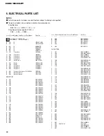

31
CDS-9036ZT
•
Note :
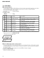
Unlike previous CD mechanism modules the grating angle of the pickup unit cannot be adjusted after the pickup
unit is changed. The pickup unit in the CD mechanism module is adjusted on the production line to match the CD
mechanism module and is thus the best adjusted pickup unit for the CD mechanism module. Changing the pickup
unit is thus best considered as a last resort. However, if the pickup unit must be changed, the grating should be
checked using the procedure below.
•
Purpose :
To check that the grating is within an acceptable range.
•
Symptoms of Mal-adjustment :
If the grating is off by a large amount symptoms such as being unable to close tracking, being unable to perform
track search operations, or track searching taking a long time, may appear.
•
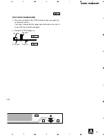
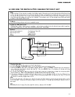
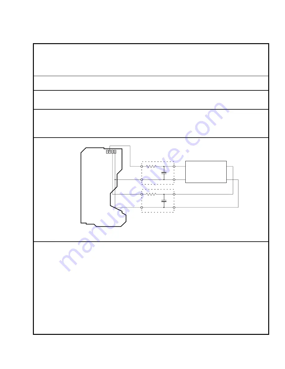
Method :
• Measuring Equipment
• Oscilloscope, Two L.P.F.
• Measuring Points
• E, F, REFOUT
• Disc
• ABEX TCD-784
• Mode
• TEST MODE
•
Checking Procedure
1. In test mode, load the disc and switch the 5V regulator on.
2. Using the
TRACK+
and
TRACK-
buttons, move the pickup unit to the innermost track.
3. Press key
RAND
to close focus, the display should read "91". Press key
TRACK-
to implement the tracking bal-
ance adjustment the display should now read "8x". Press key
RAND
4 times. The display will change, returning
to "8x" on the fourth press.
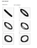
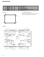
4. As shown in the diagram above, monitor the LPF outputs using the oscilloscope and check that the phase differ-
ence is within 75° . Refer to the photographs supplied to determine the phase angle.
5. If the phase difference is determined to be greater than 75° try changing the PU unit to see if there is any
improvement. If, after trying this a number of times, the grating angle does not become less than 75° then the
mechanism should be judged to be at fault.
•
Note
Because of eccentricity in the disc and a slight misalignment of the clamping center the grating waveform may be
seen to "wobble" ( the phase difference changes as the disc rotates). The angle specified above indicates the aver-
age angle.
•
Hint
Reloading the disc changes the clamp position and may decrease the "wobble".
100k
Ω
390pF
100k
Ω
390pF
E
REFOUT
F
REFOUT
Xch
Ych
OSCILLOSCOPE
L.P.F.
L.P.F.
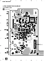
CONTROL UNIT(S7)
6.2 CHECKING THE GRATING AFTER CHANGING THE PICKUP UNIT
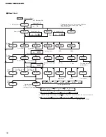
Summary of Contents for CDS-9036ZT/ES
Page 4: ...4 CDS 9036ZT 2 2 EXTERIOR ...
Page 6: ...6 CDS 9036ZT 2 4 CD MECHANISM MODULE ...
Page 11: ...11 CDS 9036ZT 5 6 7 8 5 6 7 8 D C B A A B B b ...
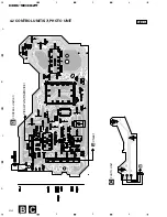
Page 12: ...12 CDS 9036ZT 1 2 3 4 2 3 4 D C B A 1 B a B a B b CONTROL UNIT S7 B PICKUP UNIT SERVICE ...
Page 13: ...13 CDS 9036ZT 5 6 7 8 5 6 7 D C B A 8 B a C B a B b C PHOTO UNIT CXB3043 ...
Page 14: ...14 CDS 9036ZT 1 2 3 4 2 3 4 D C B A 1 B b B a B b ...
Page 15: ...15 CDS 9036ZT 5 6 7 8 5 6 7 D C B A 8 B b B a B b A ...
Page 19: ...19 CDS 9036ZT ...
Page 22: ...22 CDS 9036ZT 1 2 3 4 2 3 4 D C B A 1 CONTROL UNIT A A ...
Page 23: ...23 CDS 9036ZT 5 6 7 8 5 6 7 D C B A 8 SIDE B A ...
Page 25: ...25 CDS 9036ZT D C B A 1 2 3 4 1 2 3 4 SIDE B B CONTROL UNIT S7 B C ...
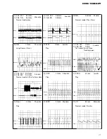
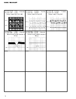
Page 32: ...32 CDS 9036ZT Grating waveform Ech Xch 20mV div AC Fch Ych 20mV div AC 45 0 75 60 30 90 ...


