


AXM-P90RS/EW5
9
5
6
7
8
5
6
7
8
C
D
F
A
B
E
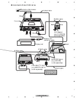
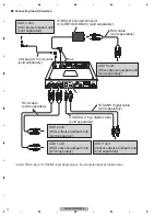
2.3 CONNECTION DIAGRAM
Translucent with black stripe
(chassis ground)
Connect to a clean, paint-free
metal location.
Fuse (4 A)
Translucent with yellow stripe
Connect to the constant
12 V supply terminal.
Red
Connect to terminal controlled
by ignition switch (12 V DC).
Yellow/black
If you use a device with a Mute function, connect
this lead to the Audio Mute lead on that device.
If not, keep the Audio Mute lead free of any connections.
Blue/white
Connect to system control
terminal of the power amp
(max. 300 mA 12 V DC).
Orange/white
Connect to lighting switch terminal.
Fuse resistor
Fuse resistor
This unit
Covering
-
Connecting the power cable
Summary of Contents for AXM-P90RS/EW5
Page 15: ...AXM P90RS EW5 15 5 6 7 8 5 6 7 8 C D F A B E ...
Page 25: ...AXM P90RS EW5 25 5 6 7 8 5 6 7 8 C D F A B E ...
Page 28: ...AXM P90RS EW5 28 1 2 3 4 1 2 3 4 C D F A B E 9 2 EXTERIOR A B C A B B C C A AXM P01_J 2_2 18 ...
Page 42: ...AXM P90RS EW5 42 1 2 3 4 1 2 3 4 C D F A B E D b D a D a D b PD6573A S 818A33AUC BGN A JA801 ...
Page 43: ...AXM P90RS EW5 43 5 6 7 8 5 6 7 8 C D F A B E D a D b D b D a 1 MXK8203 OEL MODULE ...


