


AXM-P90RS/EW5
33
5
6
7
8
5
6
7
8
C
D
F
A
B
E
A-b
A-a
A-b
A-a
A-b
A-b
A-a
A C
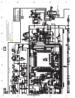
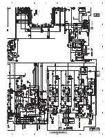
PE5612A
DIT4096IPW
ERA15-02VH
FUSE
CEK1001
ERA15-02VH
472/16
600
µ
H
ERA15-02VH
ERA15-02VH
ERA15-02VH
470/25
CEK1250
0R0
CLK for DIT
DIT_CLK
for ADJ TP
HOT side
DIT_CLK
for ADJ TP
GND
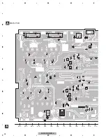
RESET VOLTAGE
It changes to 4.1V.
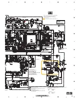
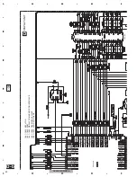
101~200 : CLOCK
201~300 : ANALOG INPUT
301~400 : IP-BUS
401~500 : DIGITAL INPUT
501~600 : DIGITAL AUDIO
601~700 : SYSTEM MICROCOMPUTER
701~800 : POWER SUPPLY
801~900 : GRILLE JOINT
901~999 : OPTICAL OUTPUT
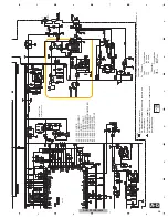
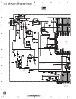
C
CONNECTOR
PCB 2
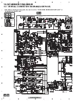
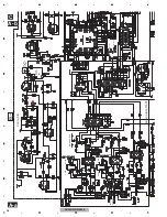
The
>
mark found on some component parts indicates
the importance of the safety factor of the part.
Therefore, when replacing, be sure to use parts of
identical designation.
Symbol indicates a resistor.
No differentiation is made between chip resistors and
discrete resistors.
NOTE :
Symbol indicates a capacitor.
No differentiation is made between chip capacitors and
discrete capacitors.
For resistors and capacitors in the circuit diagrams, their resistance values or
capacitance values are expressed in codes:
Ex. *Resistors
Code Practical value
123 12k ohms
103 10k ohms
*Capacitors
Code Practical value
103 0.01
µ
F
101/10 100
µ
F/10V
>
>
A
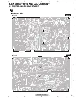
MAIN PCB
: The power supply is shown with the marked box.
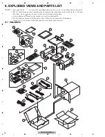
N1863
MAIN UNIT
Consists of
MAIN PCB
CONNECTOR PCB1
CONNECTOR PCB2
Summary of Contents for AXM-P90RS/EW5
Page 15: ...AXM P90RS EW5 15 5 6 7 8 5 6 7 8 C D F A B E ...
Page 25: ...AXM P90RS EW5 25 5 6 7 8 5 6 7 8 C D F A B E ...
Page 28: ...AXM P90RS EW5 28 1 2 3 4 1 2 3 4 C D F A B E 9 2 EXTERIOR A B C A B B C C A AXM P01_J 2_2 18 ...
Page 42: ...AXM P90RS EW5 42 1 2 3 4 1 2 3 4 C D F A B E D b D a D a D b PD6573A S 818A33AUC BGN A JA801 ...
Page 43: ...AXM P90RS EW5 43 5 6 7 8 5 6 7 8 C D F A B E D a D b D b D a 1 MXK8203 OEL MODULE ...


