PDP-433PU
63
5
6
7
8
5
6
7
8
C
D
F
A
B
E
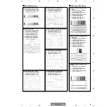
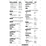
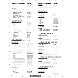
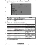
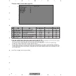
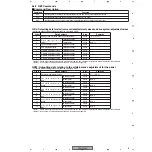
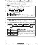
Display example of the eleventh page
No.
Item
Explanation
1
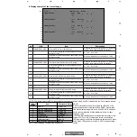
The latest PD record in the PD history
2
Accumulated operating time of the panel when Trouble
Record 1 occured
3
4
Disregard the first four-digit number. Following this
number, the information on PD is displayed.
H : hour , M : minute
Temperature at the internal thermal sensor when Trouble
Record 1 occured
Maximum temperature to be displayed : +94
°
C
11/18
TROUBLE RECORD1
The second latest PD record in the PD history
Accumulated operating time of the panel when Trouble
Record 2 occured
Disregard the first four-digit number. Following this
number, the information on PD is displayed.
H : hour , M : minute
Temperature at the internal thermal sensor when Trouble
Record 2 occured
Maximum temperature to be displayed : +94
°
C
TROUBLE RECORD2
The third latest PD record in the PD history
Accumulated operating time of the panel when Trouble
Record 3 occured
Disregard the first four-digit number. Following this
number, the information on PD is displayed.
H : hour , M : minute
Temperature at the internal thermal sensor when Trouble
Record 3 occured
Maximum temperature to be displayed : +94
°
C
TROUBLE RECORD3
The fourth latest PD record in the PD history
Accumulated operating time of the panel when Trouble
Record 4 occured
Disregard the first four-digit number. Following this
number, the information on PD is displayed.
H : hour , M : minute
Temperature at the internal thermal sensor when Trouble
Record 4 occured
Maximum temperature to be displayed : +94
°
C
TROUBLE RECORD4
5
6
7
8
9
10
11
12
13
14
15
Note: The actual page structure may be different.
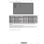
NOTE1:
A PD record representing 5 blinks of the Red LED (a PD of the
power-supply section) must display "0000 NONE", accumulated
time and temperature together. If only "0000 NONE" is displayed,
but the accumulated time and temperature are zero, it means
there was no PD.
If "0000 NONE"is displayed and the internal thermal sensor temp-
erature is 78
°
C or more, it represents a record of a shutdown
(SD) prompted by the abnormal temperature (indicated by 4 blinks
of the Green LED), and not a record of a PD of the power-supply
section.
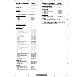
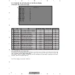
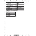
NOTE : The failure point of a PD, corresponding to the number of blinks of the Red LED, is indicated in the PD records as follows:
1
No.
2
3
4
5
6
7
8
9
10
11
12
13
14
15
16
17
18
19
1
1 / 1 8
N
PUT 1
I N
S G
I
No
DC
H
P O
:
0 0 0 0
NONE
R
T OUBLE
CORD1
RE
R
T OUBLE
CORD2
RE
R
T OUBLE
CORD3
RE
R
T OUBLE
CORD4
RE
3 5 0
5 7
M
H
+ 2 5
1 6 0 0
XDR I VE PD
3 0 0
1 5
M
H
+ 4 5
0 2 0 0
ADRK PD
2 5 0
1 9
M
H
+ 6 5
1 5 0 0
YDCDC PD
2 0 0
2 5
M
H
Number of
blinks
Item
Past record dislay
1
Y-DRIVE
2
Y-DC/DC CONVERTER
3
X-DC/DC CONVERTER
4
X-DRIVE
5
Power supply
6
Address junction
7
Address resonance
8
DIGITAL-DC/DC CONVERTER
Y-DRIVE PD
Y-DC/DC PD
X-DC/DC PD
X-DRIVE PD
0000 NONE *
1
ADR PD
ADRK PD
DCC PD

