11
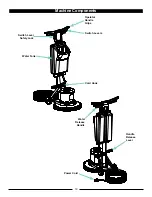
Operator Handle Grips
Use the operator handle grips to operate and move
the machine. The switch levers on the underside of
the handle grips, turn the motor on and off. Locate the
handle grips in a comfortable operating position and
lock the handle release lever in place. While operating
the machine, slightly raising or lowering the operators
handle will help the operator control the machine.
Switch Levers
The switch levers activate the switch module to turn the
motor on and off. The switch module will not activate
unless the switch lever safety lock is pressed first. To
operate the machine, only one switch lever has to be
engaged. This allows the operator to alternate hands
while using the machine. To stop the motor from turning,
release the switch levers.
Switch Lever Safety Lock
The switch lever safety lock is to prevent someone
from accidentally turning the machine on. To turn the
machine on, always make sure the handle is lowered in
the operators position and the handle release lever is
locked. Push and hold the switch lever safety lock with
one hand, while engaging one of the switch levers. Once
the machine has started, the switch lever safety lock can
be released.
Water Tank
The water tank can be filled with clean water. This
tank is for water only.
DO NOT
place any flammable,
corrosive, and/or toxic liquids and powders in the water
tank. Remove the fill cap to add water to the tank and
replace the cap to prevent splashing of water on the
electrical components during use. Always drain any
remaining water from the tank before storage.
Handle Release Lever
This handle is used to release or lock the operators
handle. Pulling up on the lever will allow the handle to
move freely. Pushing down on the lever, horizontally,
will lock the handle in place. The handle should always
be locked while in use, as well as during transport or
storage.
Cord Hook
To prevent the cord from being damaged while not is
use, wrap the cord around the cord hook and the top of
the operators handle.
Water Release Handle
Pulling up on this handle will open the valve inside the
tank and allow water to flow from the water tank to
the driver. Water will only flow from the tank while the
handle is raised. To stop the flow of water from the tank,
release the handle. The amount of flow can be varied by
how far the handle is raised.
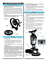
To drain the water tank, place the machine over a drain.
Remove the fill cap and use the water release handle to
drain the tank. Replace fill cap when finished.
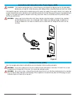
Power Cord
Use only the supplied power cord with this machine. The
power cord is sized to be used with this machine. To
attach the power cord to the machine, insert plug on the
back of handle into the female receptacle of the power
cord. Properly align the plug pins with the holes of the
receptacle, push together and twist to lock the cords in
place.
Summary of Contents for PE225FP
Page 1: ...1 Floor Polisher PE225FP Operator s Manual...
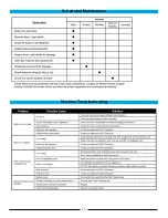
Page 13: ...13 Machine Troubleshooting Scheduled Maintenance...
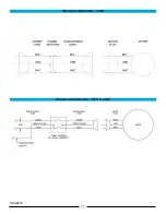
Page 15: ...15 Electrical Schematic 120V Electrical Schematic 127V 230V RF068800...
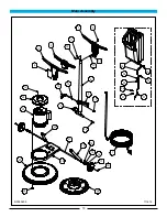
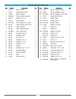
Page 20: ...20 Handle Assembly 225FP E E6 Models RF071600 060917 4 6 3 2 11 10 1 7 9 1 5 12 8...
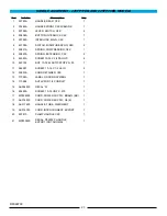
Page 22: ...22 HANDLE ASSEMBLY 225FP17EB AND 225FP20EB MODELS RF066700...


