background image

Operating Manual

1

Contents

Introduction

2

Validity of the documentation

2

Overview

2

Intended use

3

System requirements

3

CPU versions

3

System software versions

3

Functions

5

Inputs

5

Detecting signals at the inputs

5

Signal change behaviour

6

Outputs

7

Test pulse outputs

9

Schematic internal wiring diagram

10

Operation of the module on SafetyBUS p

10

Supply voltage

12

Display elements

13

Installation

14

Commissioning

15

Recommissioning

15

Faults

15

Check list for commissioning

16

Module configuration

17

Technical details

18

Changes in the documentation

21

PSS SB DI8O8

Artisan Technology Group - Quality Instrumentation ... Guaranteed | (888) 88-SOURCE | www.artisantg.com

Summary of Contents for PSS Series

Page 1: ...ess underutilized and idle equipment along with credit for buybacks and trade ins Custom engineering so your equipment works exactly as you specify Critical and expedited services Leasing Rentals Demos In stock Ready to ship TAR certified secure asset solutions Expert team I Trust guarantee I 100 satisfaction All trademarks brand names and brands appearing herein are the property of their respecti...

Page 2: ...The spirit of safety Programmable Safety Systems PSS Range PSS SB DI8O8 Operating Manual Item No 19 964 12 Artisan Technology Group Quality Instrumentation Guaranteed 888 88 SOURCE www artisantg com ...

Page 3: ...tation will be gratefully received The names of products goods and technologies used in this documentation are registered trademarks of the respective companies Automation Workbench Pilz PIT PMI PNOZ Primo PSS SafetyBUS p are registered trademarks of Pilz GmbH Co KG Artisan Technology Group Quality Instrumentation Guaranteed 888 88 SOURCE www artisantg com ...

Page 4: ...behaviour 6 Outputs 7 Test pulse outputs 9 Schematic internal wiring diagram 10 Operation of the module on SafetyBUS p 10 Supply voltage 12 Display elements 13 Installation 14 Commissioning 15 Recommissioning 15 Faults 15 Check list for commissioning 16 Module configuration 17 Technical details 18 Changes in the documentation 21 PSS SB DI8O8 Artisan Technology Group Quality Instrumentation Guarant...

Page 5: ...ess switch on the unit Inputs on the module can be allocated to two I O groups There are 6 positive and 2 negative switching 2 A outputs Two of the positive switching outputs can be used in conjunction with two negative switching outputs one each to form two dual pole outputs Individually the negative switching outputs can only be used for non safety related applications in which it is permitted t...

Page 6: ...le which has been designed for use as an input output device on SafetyBUS p System requirements CPU versions The PSS SB DI8O8 is supported by all SafetyBUS p compatible safety systems in the PSS range System software versions The following system software is required in order to configure the module PSS WIN PRO from version 1 0 0 Artisan Technology Group Quality Instrumentation Guaranteed 888 88 S...

Page 7: ...O7 I7 12 9 1 3 2 4 5 6 7 8 10 11 7 1 Switch for setting the device address on SafetyBUS p 2 Labelling strip for the I Os 3 SafetyBUS p interface 4 LEDs for operating status and supply voltage 5 Status LEDs for the I Os 6 Terminal block for dedicated test pulses 7 Terminal blocks for I Os 8 Connection terminal for the functional earth 9 Terminal block for the supply voltage 10 Terminal block for Gr...

Page 8: ... up to and including category 2 in accordance with EN 954 1 in the case of dual channel input devices this extends to category 3 applications The device should be suitably wired to eliminate the risk of a short circuit in the external wiring between the different inputs and a short to the Supply or Load Supply Test pulses must be used for applications with single channel input devices above catego...

Page 9: ...he configured signal change behaviour Two behaviour modes may be defined Default The signal change is not registered Fast Each signal change is stored in a FIFO telegram buffer If the acknowledgement telegram arrives the module will send an Event Telegram from the FIFO telegram buffer for each signal change detected 1 Signal 0 Signal t1 t1 t t2 U t1 Pulse length for guaranteed signal detection for...

Page 10: ...also possible to wire outputs O0 O1 O2 or O3 to a negative switching output to form a dual pole output both outputs would then have to be managed separately within the user pro gram If the PSS master sends a 1 signal to a positive switching output via SafetyBUS p the PSS SB DI8O8 will supply approx 24 VDC to the relevant output which will show high impedance at a 0 signal Negati ve switching outpu...

Page 11: ...ions To achieve category 4 dual actuators must be connected to two different outputs 1 Signal t2 t1 t1 t3 t1 t t3 t1 U 0 Signal t1 Pulse length for switch on test 200 µs t2 Repetition time under certain circumstances 6 5 10 ms t3 Scan time for switch on test ca 2 m WARNING When wiring an output with capacitance you must be aware of the following An output that is switched off is tested by switchin...

Page 12: ...es on or off In accordance with EN 954 1 category 2 or higher can be achieved with such an output An output test can be performed in the user program in order to reduce fault detection time If the output is switched on proceed as follows at a non critical point in the program switch the output off and then on again for one PSS cycle Follow the process in reverse if the output is switched off If th...

Page 13: ...n either have Section A alone or both Section A and Section B Outputs always belong to Section A In the system software you can configure a limit value to determine which section inputs will belong to those with a number below this limit will belong to Section A those with a higher number will belong to Section B The I O addresses which the PSS master uses to address the I Os are established accor...

Page 14: ...T0 I7 O7 I6 O6 I5 O5 I4 O4 I3 O3 I2 O2 I1 O1 I0 O0 T1 T1 T0 T0 Ground Load Supply Supply Supply Ground Load Supply O4 O5 6 6 nF 3 3 nF 2 4 M Schematic internal wiring diagram of the PSS SB DI8O8 Artisan Technology Group Quality Instrumentation Guaranteed 888 88 SOURCE www artisantg com ...

Page 15: ...the module on SafetyBUS p The advantage in separating the two supply voltages Supply and Load Supply is best seen in the following example Several machines are secured by the same safety devices Each of these machines is assigned a PSS SB DI8O8 module One power supply feeds all the Supply modules and the general safety devices Each machine also has a separate supply voltage Load Supply Each unit i...

Page 16: ... off a system error is preventing the module from starting up LED SB active Indicates a connection between the module and the management device Green Successfully connected to management device LED off no connection to SafetyBUS p faulty wiring or management device not in operation LED flashing Connection made to SafetyBUS p but the management device does not recognise the module invalid device ad...

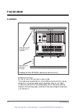
Page 17: ... O6 I6 O7 I7 Free space for rail mounting and for ventilation Recommended free space for wiring Installation Dimensions in mm H x W x D 140 x 170 x 65 5 51 x 6 69 x 2 56 The module can be attached to a 35 mm DIN rail top hat rail or can be screwed on to mounting plate using fixing bolts order no 311 068 To affix the module on to a mounting plate drill 2 x M4 holes internal thread in the mounting p...

Page 18: ...n occur This is the only way to check whether an output has been incorrectly excluded from the output test and whether the output test that has been programmed is effective Recommissioning NOTICE If the device has to be recommissioned you may experience errors when inserting the terminal blocks as these are not designed to be exchanged To ensure such errors are eliminated always carry out a functi...

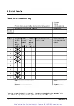
Page 19: ...n in Error simulated as dual related from case of error for safety related pole output output output1 output test yes no yes no yes no O0 O1 O2 O3 O4 O5 O6 O7 Date Date Signed Signed 1 Wait until the user program sets the output to 1 output s LED will light and then generate a short circuit between the output and 24 V The required error reaction should then occur Artisan Technology Group Quality I...

Page 20: ...ration The procedure for configuring SafetyBUS p and the PSS SB DI8O8 module is described in the online help of the PSS WIN PRO system software Artisan Technology Group Quality Instrumentation Guaranteed 888 88 SOURCE www artisantg com ...

Page 21: ...screw connectors SafetyBUS p Transmission rate Max 500 kBit s Cable runs Max 3500 m Transmission type Differential two wire cable Fibre optic cabale via fibre optic coupler Connection 9 pin D Sub connector Digital inputs Number of inputs 8 Potential isolation Yes from SafetyBUS p Signal level at 1 high 15 30 VDC Signal level at 0 low 3 5 VDC Input current Typ 6 mA Input delay 1 ms Pulse suppressio...

Page 22: ...ted range 0 2 5 A Short circuit protection Electronic Limitation of inductive switch off Approx 60 VDC Simultaneity 100 Residual current at 0 signal 0 mA Signal level at the outputs 0 signal UB 1 signal and 2 5 A load 1 VDC Output switch delay 50 µs Off time during self test 200 µs On time during self test 200 µs Status indicator Green LED Dedicated test pulses Supply From the module supply Number...

Page 23: ...permitted Vibration EN 60068 2 6 Frequency range 10 150 Hz max 1g Vibration resistance EN 60068 2 27 15g 11 ms EMC EN 61000 6 2 EN 55011 A Mechanical data Weight 530 g Dimensions H x W x D 140 x 170 x 65 mm The names of products goods and technologies are trademarks of the respective companies The version of the standards current at 2004 04 shall apply Artisan Technology Group Quality Instrumentat...

Page 24: ...of the switch for setting the device address was amended 14 14 Procedure when adding a module to the bus structure was amended Changes from version III to version IV Old New Change p no p no 3 3 Labelling strip for inputs and outputs 4 5 12 4 5 12 If an error occurs outputs are switched off first and then the error telegram is sent 6 6 Category 2 in accordance with EN 954 1 can be achieved using o...

Page 25: ...ed Changes from version VI to version VII Old New Change p no p no 4 New section Detecting signals at the inputs All subsequent sections moved forward 5 New information on device s reaction when using capacitive loads 1µF 6 New section under WARNING with timing diagram 20 20 New version information under Transmission rate Changes from version VII to version VIII Old New Change p no p no 4 4 Pulse ...

Page 26: ...Changes from version IX to version X Old New Change p no p no 2 Validity of the documentation 6 signal change behaviour 20 21 signal change behaviour 21 22 Power Consumtion Supply 21 22 fibre optic couplers can now be connected to the SafetyBUS p interface Changes in version 19 964 11 Old New Change p no p no pulse suppression 500 µs Artisan Technology Group Quality Instrumentation Guaranteed 888 ...

Page 27: ... Norms updated 3 New section System requirements 6 INFO deleted 17 21 17 Module configuration 20 20 Technical details was amended 20 New The version of the standards current at 2004 04 shall apply Artisan Technology Group Quality Instrumentation Guaranteed 888 88 SOURCE www artisantg com ...

Page 28: ... 3409 0 Telefax 49 711 3409 133 E Mail pilz gmbh pilz de www pilz com 49 711 3409 444 In many countries we are represented by sales partners Please refer to our Homepage for further details or contact our headquarters 19 964 12 2006 01 Printed in Germany Artisan Technology Group Quality Instrumentation Guaranteed 888 88 SOURCE www artisantg com ...

Page 29: ...quipment Have surplus equipment taking up shelf space We ll give it a new home Learn more Visit us at artisantg com for more info on price quotes drivers technical specifications manuals and documentation Artisan Scientific Corporation dba Artisan Technology Group is not an affiliate representative or authorized distributor for any manufacturer listed herein We re here to make your life easier How...

Reviews: