


1002904-EN-03
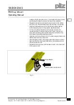
PSEN op Mirror/1
Operating Manual
2
Pilz GmbH & Co. KG, Felix-Wankel-Straße 2, 73760 Ostfildern, Germany
Telephone: +49 711 3409-0, Telefax: +49 711 3409-133, E-Mail: [email protected] Original document
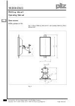
Assembly
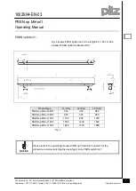
Fig. 1 shows a protection system that consists of a light curtain and
two deviating mirrors. The alignment of deviating mirrors is
explained in the following sections based on this example.
Fig. 1
Stand-alone installation
The mounting bracket kit PSEN op Mirror Bracket Kit/1
and a floor
bracket are required for installation.
Define the area to be protected and the exact positions where the
deviating mirrors and the transmitter and receiver units of the light
curtain are to be installed.
Fix the floor bracket to the defined point on the floor and note that
their axes have to be aligned vertically.
Install the deviating mirrors at the floor brackets, and the
transmitter and receiver units, taking into account the notes
above. Insert the screw M6x50 into the slot hole of the rail, then
screw it in with the corresponding washer and nut (Fig. 2) to
install the mounting bracket at the deviating mirrors.
Align the deviating mirror to ca. 45° to the optical path.
Position the laser pointer at the upper part of the transmitter unit
and align the unit so that the laser beam is horizontally in the
Transmitter
deviating
mirrors
deviating
mirrors
Receiver