background image

Operation

Operating Manual PNOZ mm0.1p
1002101-EN-04

29

INFORMATION

Use the rotary knob to exit the error stack.

Procedure for reading the error stack with the PNOZmulti Configurator:

}

See online help for the PNOZmulti Configurator

Summary of Contents for PNOZ mm0.1p

Page 1: ...PNOZ mm0 1p Operating Manual 1002101 EN 04 Configurable compact control systems PNOZmulti Mini...

Page 2: ...umentation will be gratefully received Source code from third party manufacturers or open source software has been used for some components The relevant licence information is available on the Interne...

Page 3: ...unction description 12 4 1 Integrated protection mechanisms 12 4 2 Functions 12 4 3 System reaction time 12 4 4 Diagnostics 12 4 5 Block diagram 13 Section 5 Installation 14 5 1 Control cabinet instal...

Page 4: ...26 7 2 2 Switch between menu levels 27 7 2 3 Unit diagnostics on the LC display 27 7 2 4 Error stack on the LC display 28 Section 8 Technical details 30 8 1 Safety characteristic data 33 Section 9 Su...

Page 5: ...is particularly important is identified as follows DANGER This warning must be heeded It warns of a hazardous situation that poses an immediate threat of serious injury and death and indicates preven...

Page 6: ...Introduction Operating Manual PNOZ mm0 1p 1002101 EN 04 6 INFORMATION This gives advice on applications and provides information on special fea tures...

Page 7: ...safety outputs Depending on the application up to PL e of EN ISO 13849 1 and up to SIL CL 3 of EN IEC 62061 12 inputs for connecting for example E STOP pushbuttons Two hand button Safety gate limit sw...

Page 8: ...e safety outputs Plug in connection terminals Either spring loaded terminal or screw terminal available as an accessory see order reference Rotary knob for menu control Expansion modules can be connec...

Page 9: ...21 M22 M23 IM0 IM1 IM2 I6 I5 I4 IM3 I7 I8 I9 I10 I14 I13 I12 I11 I15 T0 T1 T2 O2 O1 O0 T3 O3 IM16 IM17 IM18 0 V A2 A1 IM19 24 V M20 M21 M22 M23 Front view with and without cover Legend X1 Inputs I8 I1...

Page 10: ...se interference if installed in other environments If installed in other environments measures should be taken to comply with the applicable standards and directives for the respective installation si...

Page 11: ...ng followed the guidelines in the manual Operating personnel are not suitably qualified Any type of modification has been made e g exchanging components on the PCB boards soldering work etc 3 3 4 Disp...

Page 12: ...r each other They evaluate the input circuits on the base unit and expansion modules and switch the outputs on the base unit and expansion modules accordingly The LEDs on the base unit and expansion m...

Page 13: ...5 Block diagram Power A1 A2 Input Configurable output 24 V 0 V 24 V 0 V T1M21 O2 O0 O1 O3 IM1 I8 I5 I11 I4 I9 I12 I13 I14 I15 I7 I6 I10 IM2 IM0 IM3 IM16 IM18 IM17 IM19 Interface extension module USB I...

Page 14: ...before lifting it from the mounting rail To comply with EMC requirements the mounting rail must have a low impedance con nection to the control cabinet housing NOTICE Damage due to electrostatic disch...

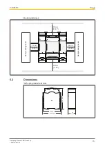
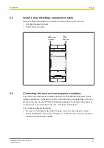
Page 15: ...20 mm 0 787 20 mm 0 787 IM0 IM1 IM2 I6 I5 I4 IM3 I7 I8 I10 I14 I13 I12 I11 I15 X3 X1 X4 X2 PNOZ mm0 1p T0 T1 T2 O2 O1 O0 T3 O3 IM16 IM17 IM18 0 V A2 A1 IM19 24 V M20 M21 M22 M23 Heat producing device...

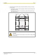
Page 16: ...ion of the expansion modules is defined in the PNOZmulti Configurator The ex pansion modules are connected to the left or right of the base unit depending on the type Please refer to the document PNOZ...

Page 17: ...odule Left hand side on the base unit and expansion modules to the left of the base unit Black yellow terminator Right hand side on the base unit and expansion modules to the right of the base unit Ye...

Page 18: ...ways be supplied by a single power supply The power supply must meet the regulations for extra low voltages with protective sep aration Test pulse outputs must exclusively be used to test the inputs T...

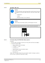
Page 19: ...ing the chip card Make sure that you do not bend the chip card as you insert it into the chip card slot 6 2 3 Commissioning the PNOZmulti safety system Procedure Wire the inputs and outputs on the bas...

Page 20: ...Once the project has been successfully downloaded the status of the inputs and outputs will be shown on the display 6 2 3 2 Load project via USB port Procedure Insert a chip card into the card slot o...

Page 21: ...E STOP with detection of shorts across contacts IM0 T0M20 S1 S1 T1M21 IM1 T0M20 IM0 Start circuit Input circuit without detection of shorts across contacts Input circuit with detection of shorts acro...

Page 22: ...arate multicore cables Please note that in the event of an error in the feedback loop the safety system switches to a safe condition and shuts down all the outputs Feedback loop Redundant output Conta...

Page 23: ...or on the base unit outputs e g short across the contacts leading to a safe condition Internal error on the base unit Internal error on the base unit inputs Internal error on the base unit outputs Bas...

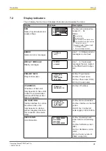
Page 24: ...PROJECT INFO Project information PNOZ mm0p project CRC 0x8108 09 02 2009 1st line Project name 2nd line Project name 3rd line Check sum CRC 4th line Creation date IP ADDRESS IP address of base unit on...

Page 25: ...line Error number EN and error parameter PA 4th line Continuation of er ror parameter PA INTERFACE Port only appears on base units to which a communication module is connected Interface USB Show selec...

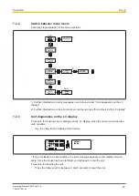
Page 26: ...ob can remain within the unit 7 2 1 2 Pull out and retract the knob 1 2 Pull out knob A until it locks into position Release knob B and push it back into the unit Press the bar on the side of the knob...

Page 27: ...ormation on the error stack can be found under Error stack on the LC display 7 2 3 Unit diagnostics on the LC display Procedure for showing error messages on the LC display when the errors do not lead...

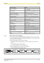
Page 28: ...level SUPPLY HIGH Supply voltage exceeds the tolerance level RELAY DEVICE Error on the expansion module with relay outputs RELAY DEVICE OR TERMINATION PLUG Error on the expansion module with relay ou...

Page 29: ...ating Manual PNOZ mm0 1p 1002101 EN 04 29 INFORMATION Use the rotary knob to exit the error stack Procedure for reading the error stack with the PNOZmulti Configurator See online help for the PNOZmult...

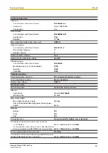
Page 30: ...15 20 Output of external power supply DC 192 0 W Status indicator Display LED Configurable inputs outputs inputs or auxiliary outputs Number 8 Galvanic isolation No Configurable inputs Input voltage...

Page 31: ...proof yes Test pulse outputs Number of test pulse outputs 4 Voltage 24 V Current 0 1 A Max duration of off time during self test 5 ms Short circuit proof yes Potential isolation No Times Switch on del...

Page 32: ...lation Potential isolation between SC output and system voltage Type of potential isolation Basic insulation Rated surge voltage 2500 V Mechanical data Mounting position Horizontal on top hat rail DIN...

Page 33: ...62061 SIL CL EN 62061 PFHD 1 h EN ISO 13849 1 2015 TM year Logic CPU 2 channel PL e Cat 4 SIL CL 3 1 54E 09 20 Expansion right PL e Cat 4 SIL CL 3 2 13E 10 20 Expansion left PL e Cat 4 SIL CL 3 2 38E...

Page 34: ...002101 EN 04 34 INFORMATION A safety function s SIL PL values are not identical to the SIL PL values of the units that are used and may be different We recommend that you use the PAScal software tool...

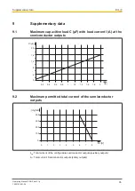
Page 35: ...A at the semiconductor outputs 4 8 12 16 20 0 0 2 0 4 0 6 0 8 1 1 2 1 4 1 6 1 8 2 I A C F 9 2 Maximum permitted total current of the semiconductor outputs 100 200 300 400 0 1 2 3 4 5 6 7 8 IHL A ICfg...

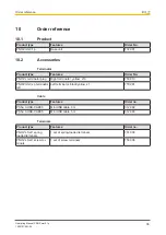
Page 36: ...rminator plug Right terminator yellow x10 750 010 PNOZ mm0 xp terminator left Left terminator black yellow x1 779 261 Cable Product type Features Order no PSSu A USB CAB03 Mini USB cable 3 m 312 992 P...

Page 37: ...p ThE SPIrIT Of SAfETY are registered and protected trademarks of Pilz Gmbh Co KG in some countries We would point out that product features may vary from the details stated in this document dependin...

Reviews: