Pilz PNOZ m ES CANopen Operating Manual Download Page 9

Safety

Operating Manual PNOZ m ES CANopen
1002699-EN-06

9

3

Safety

3.1

Intended use

The fieldbus module PNOZ m ES CANopen is an expansion module of the configurable
control system PNOZmulti 2. It is used for communication between the configurable control
system PNOZmulti 2 and CANopen.
CANopen is designed for fast data exchange at field level. The expansion module PNOZ m
ES CANopen is a passive CANopen subscriber (Slave). The basic communication func-
tions with CANopen conform to the guidelines of the CANopen User Group CiA DS-301
V4.2.0. The central controller (master) reads input information from the slaves and writes
output information to the slaves as part of each cycle. As well as the cyclical transfer of us-
able data, the expansion module PNOZ m ES CANopen also has diagnostic and commis-
sioning functions. Data traffic is monitored on the Master/Slave side.

The expansion module may only be connected to a base unit from the configurable system
PNOZmulti 2 (please refer to the document "PNOZmulti System Expansion" for details of
the base units that can be connected).

The configurable system PNOZmulti 2 is used for the safety-related interruption of safety
circuits and is designed for use in:

}

Emergency stop equipment

}

Safety circuits in accordance with VDE 0113 Part 1 and EN 60204-1

The expansion module may not be used for safety-related functions.

The following is deemed improper use in particular:

}

Any component, technical or electrical modification to the product

}

Use of the product outside the areas described in this manual

}

Use of the product outside the technical details (see 

Technical details [

 20]

).

NOTICE

EMC-compliant electrical installation

The product is designed for use in an industrial environment. The product
may cause interference if installed in other environments. If installed in other
environments, measures should be taken to comply with the applicable
standards and directives for the respective installation site with regard to in-
terference.

3.2

System requirements

Please refer to the "Product Modifications PNOZmulti" document in the "Version overview"
section for details of which versions of the base unit and PNOZmulti Configurator can be
used for this product.

Summary of Contents for PNOZ m ES CANopen

Page 1: ...PNOZ m ES CANopen Operating Manual 1002699 EN 06 Configurable control systems PNOZmulti 2...

Page 2: ...umentation will be gratefully received Source code from third party manufacturers or open source software has been used for some components The relevant licence information is available on the Interne...

Page 3: ...Section 4 Function description 11 4 1 Operation 11 4 2 Data access 11 4 3 Block diagram 12 Section 5 Installation 13 5 1 General installation guidelines 13 5 2 Dimensions in mm 13 5 3 Connect the bas...

Page 4: ...Contents Operating Manual PNOZ m ES CANopen 1002699 EN 06 4 Section 9 Order reference 22 9 1 Product 22 9 2 Accessories 22...

Page 5: ...n that is particularly important is identified as follows DANGER This warning must be heeded It warns of a hazardous situation that poses an immediate threat of serious injury and death and indicates...

Page 6: ...Introduction Operating Manual PNOZ m ES CANopen 1002699 EN 06 6 INFORMATION This gives advice on applications and provides information on special fea tures...

Page 7: ...Transmission rate selected via rotary switch 1 MBit s 10 kbit s 125 kBit s 20 kbit s 250 kBit s 50 kbit s 500 kBit s 800 kbit s Status indicators for communication with CANopen and for errors 128 vir...

Page 8: ...Front view 1 3 2 4 Legend 1 LED Power Run Error 2 Rotary switch DR Transmission rate X10 Tens digit for the station address X1 Units digit for the station address 3 X1 CANopen interface male 9 pin D...

Page 9: ...NOZmulti System Expansion for details of the base units that can be connected The configurable system PNOZmulti 2 is used for the safety related interruption of safety circuits and is designed for use...

Page 10: ...y and liability All claims to warranty and liability will be rendered invalid if The product was used contrary to the purpose for which it is intended Damage can be attributed to not having followed t...

Page 11: ...n The values for the inputs are set as an output in the Master and transferred to the PNOZmulti 2 Output range PNOZ m ES CANopen The outputs are configured in the PNOZmulti Configurator and transferre...

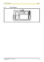
Page 12: ...Function description Operating Manual PNOZ m ES CANopen 1002699 EN 06 12 4 3 Block diagram Interface to next module Data ST CANopen Interface to previous module 24 V 0 V Module Supply...

Page 13: ...secured using a fixing element e g retaining bracket or end angle Open the locking slide before lifting the unit from the mounting rail To comply with EMC requirements the mounting rail must have a lo...

Page 14: ...r to the expansion module Install the expansion module in the position in which it is configured in the PNOZmulti Configurator The position of the expansion modules is defined in the PNOZmulti Configu...

Page 15: ...the mounting rail is not connected to the functional earth Always connect the mounting rail to the protective earth via an earthing terminal This will be used to dissipate hazardous voltages in the ca...

Page 16: ...must be used to connect the interfaces Termination CANopen To minimise cable reflection and to guarantee a defined rest signal on the transmission line CANopenmust be terminated at both ends 6 2 Sett...

Page 17: ...is set between 0 99 decimal via two rotary switches x1 and x10 1 2 3 4 9 8 7 6 0 5 x10 On the middle rotary switch x10 use a small screwdriver to set the tens digit for the ad dress 3 in the example 1...

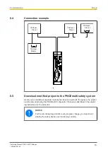
Page 18: ...project to the PNOZmulti safety system As soon as an additional expansion module has been connected to the system the project must be amended using the PNOZmulti Configurator Proceed as described in...

Page 19: ...ror message External Error is sent to the Master 7 1 1 Display elements for device diagnostics Legend LED off LED flashes 1 LED flashes once 2 LED flashes twice 3 LED flashes three times LED on LED Me...

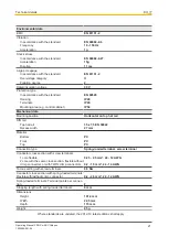
Page 20: ...W Status indicator LED Fieldbus interface Fieldbus interface CANopen Device type Slave Log CiA 301 V4 2 0 Station address 0 99d Transmission rates 1 MBit s 10 kbit s 125 kBit s 20 kbit s 250 kBit s 5...

Page 21: ...Horizontal on top hat rail DIN rail Top hat rail 35 x 7 5 EN 50022 Recess width 27 mm Material Bottom PC Front PC Top PC Connection type Spring loaded terminal screw terminal Conductor cross section w...

Page 22: ...Features Order No PNOZ mm0 xp connector left Jumper yellow black to connect the modules 10 piece 779 260 Connection terminals Product type Features Order no Spring terminals PNOZ mmcxp 1 pc Spring loa...

Page 23: ...NET p THE SPIRIT OF SAFETY are registered and protected trademarks of Pilz GmbH Co KG in some countries We would point out that product features may vary from the details stated in this document depen...

Reviews: