background image

Safety

Operating Manual PMD s10
22092-EN-05

| 8

}

Operating personnel are not suitably qualified,

}

Any type of modification has been made (e.g. exchanging components on the PCB
boards, soldering work etc.).

2.2.3

Disposal

}

When decommissioning, please comply with local regulations regarding the disposal of
electronic devices (e.g. Electrical and Electronic Equipment Act).

2.3

For your safety

The unit meets all the necessary conditions for safe operation. However, please note the
following:

}

Transport, storage and operating conditions should all conform to EN 60068-2-6 (see
"Technical details"). The unit must be disposed of properly when it reaches the end of its
service life.

}

Sufficient protection must be provided on all output contacts with capacitive and inductive
loads.

}

Note for overvoltage category III:
If voltages higher than low voltage (>50 V AC or >120 V DC) are present on the unit, con-
nected control elements and sensors must have a rated insulation voltage of at least 
250 V

Summary of Contents for PMD s10

Page 1: ...PMD s10 Operating Manual 22092 EN 05 Monitoring relays ...

Page 2: ...enta tion will be gratefully received Source code from third party manufacturers or open source software has been used for some components The relevant licence information is available on the Internet on the Pilz homepage Pilz PIT PMI PNOZ Primo PSEN PSS PVIS SafetyBUS p SafetyEYE SafetyNET p the spirit of safety are registered and protected trademarks of Pilz GmbH Co KG in some countries SD means...

Page 3: ... 16 7 3 2 Circuit for three phase motor with CT and VT 17 7 3 3 Circuit for motor 1 AC 18 7 3 4 Circuit for motor 1 AC with CT 19 7 4 Read and set parameters 19 7 5 Display menu Configuration 19 7 5 1 Rotary knob 19 7 5 2 Display 20 7 5 3 Use chip card 20 7 5 3 1 Insert chip card 21 7 5 3 2 Write data to chip card 22 7 5 3 3 Read data from chip card 22 7 5 3 4 Transfer device parameters 22 7 5 4 M...

Page 4: ...Contents Operating Manual PMD s10 22092 EN 05 4 8 Operation 30 8 1 Status messages 30 8 1 1 Error messages 30 9 Technical details 31 10 Order reference 35 11 EC declaration of conformity 36 ...

Page 5: ...ation that is particularly important is identified as follows DANGER This warning must be heeded It warns of a hazardous situation that poses an immediate threat of serious injury and death and indicates preventive measures that can be taken WARNING This warning must be heeded It warns of a hazardous situation that could lead to serious injury and death and indicates preventive measures that can b...

Page 6: ...Introduction Operating Manual PMD s10 22092 EN 05 6 INFORMATION This gives advice on applications and provides information on special fea tures ...

Page 7: ...afety regulations 2 2 1 Use of qualified personnel The products may only be assembled installed programmed commissioned operated maintained and decommissioned by competent persons A competent person is a qualified and knowledgeable person who because of their train ing experience and current professional activity has the specialist knowledge required To be able to inspect assess and operate device...

Page 8: ... unit meets all the necessary conditions for safe operation However please note the following Transport storage and operating conditions should all conform to EN 60068 2 6 see Technical details The unit must be disposed of properly when it reaches the end of its service life Sufficient protection must be provided on all output contacts with capacitive and inductive loads Note for overvoltage categ...

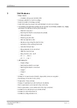
Page 9: ...ocation of switching threshold to relay Hysteresis of the switching thresholds Automatic manual reset Range selection for Uout and Iout Offset for Uout and Iout Relay function norm on off CT 1 1 1000 1 VT 1 1 100 1 LED display for Supply voltage Switching threshold for overload Switching threshold for underload Output 1 Output 2 Error Display for measured value indicator diagnostics and menu navig...

Page 10: ...gram Operating Manual PMD s10 22092 EN 05 10 4 Block diagram Insulation between the non marked area and the relay contacts Basic insulation over voltage category III Protective separation overvoltage category II ...

Page 11: ...n external current transformer Voltage transformer VT With constant voltage 500 V the voltage has to be measured via an external voltage transformer Po function K1 overload If the measured true power exceeds the switching threshold Po the LED max is lit Once the reaction time has elapsed tr the auxiliary contact switches default relay K1 and the Out 1 LED is lit Pwo function overload warning thres...

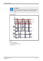
Page 12: ...asured values contain harmonics or are not sinusoidal discrepan cies may occur between the calculated true power and the actual true power Function diagram 1 tstart tstart tstart tstart Hysteresis Hysteresis Legend P Actual true power tstart Start up suppression time tr Reaction time ...

Page 13: ...able When simultaneously using an external current and an external voltage transformer the selectable measuring range limit value is calculated from the following formula Pmax 1 0 W 11 5 kW x CT x VT Examples 1 Current transformer CT 100 1 and no voltage transformer VT 1 1 Pmax 1 0 W 11 5 kW x 100 x 1 100 W 1 5 MW 2 Current transformer CT 1000 1 and voltage transformer VT 100 1 Pmax 1 0 W 11 5 kW ...

Page 14: ...of at least IP54 Use the notch on the rear of the unit to attach it to a mounting rail In environments exposed to heavy vibration or when installing on a vertical mounting rail 35 mm the unit should be secured using a fixing element e g retaining bracket or end angle Push the unit upwards or downwards before lifting it from the mounting rail ...

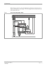
Page 15: ...o A1 A2 Single phase Measuring voltage UM Connect to terminals L1 and L2 Link terminals L1 K1 Measuring circuit Connect phase L1 of the motors to terminal U I1 Three phase Measuring voltage UM Connect to terminals L1 L2 and L3 Link terminals L1 K1 L3 K3 Measuring circuit Connect phase L1 of the motor to terminal U I1 phase L2 to ter minal L2 and L3 to W I3 Please refer to the connection diagrams f...

Page 16: ...as to be measured via an ex ternal current transformer With voltage 500 V the voltage has to be measured via an ex ternal voltage transformer 7 3 1 Circuit for three phase motor L1 L2 L3 U V W M1 K1 M3 PE N 12 14 11 A1 L2 U I1 U IN 12A L3 A2 24 22 21 Y1 Y2 I 0V W I3 K3 L1 K1 24V 0V A V H2 K1 PMD s10 Reset extern ...

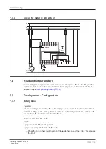
Page 17: ...Commissioning Operating Manual PMD s10 22092 EN 05 17 7 3 2 Circuit for three phase motor with CT and VT U X x u U X x u U X x u Reset extern PMD s10 ...

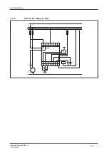
Page 18: ...Commissioning Operating Manual PMD s10 22092 EN 05 18 7 3 3 Circuit for motor 1 AC ...

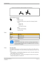
Page 19: ...s from the display and use the rotary knob to set parameters see Sample configuration 28 7 5 Display menu Configuration 7 5 1 Rotary knob Function The menu settings are made on the unit s display via a rotary knob You have the option to make the settings on the knob by hand or with a screwdriver If you make the settings with a screwdriver the knob can remain within the unit Pull out and retract th...

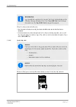
Page 20: ...ON Once an action has been taken in the menu the display switches back to the default display if a value is not set or modified within 30 s The current setting remains unchanged 7 5 3 Use chip card The parameters that are set on a unit can be stored on the chip card The data is stored along with a device identifier We recommend that you always operate the unit with a chip card If the parameters on...

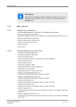
Page 21: ...l Unit parameters are automatically saved to the chip card during operation As a result the chip card always contains a copy of the unit s current internal data Exception If you select Write SIM no 7 5 3 1 Insert chip card NOTICE The chip card contact is only guaranteed if the contact surface is clean and undamaged For this reason please protect the chip card s contact surface from Contamination C...

Page 22: ...erting a chip card which has not yet been written by a PMD s10 you have the option to Allow data to be read from the chip card Insert chip card Data on chip card different to data on unit 1 select 2 Data is read into the unit Power P Load SIM no Load SIM yes Power P Do not allow data to be read from the chip card Insert chip card Data on chip card differ ent to data on unit 1 Data is not read into...

Page 23: ...sis Hyst Value for automatic reset of the fault status see function diagram Range selection for Uout Range selection for lout Offset output voltage Uoffset Selectable offset for the output voltage Uout Offset output current Ioffset Selectable offset for the output current Iout Switching threshold allocation Rel K1 Allocation of switching thresholds to auxiliary contact K1 Switching threshold alloc...

Page 24: ...enu Operating hours tOperate Operating hours of the PMD s10 Operating hours load generator tLoad Operating hours of the load generators can be reset Max voltage applied Umax highest voltage to have been applied Max current applied Imax highest current to have been applied Cycles for relay K1 K1 cycle Cycles for relay K2 K2 cycle Software version Software ...

Page 25: ...tion Power P W Settings Advanced Settings Info Display Power P W Display Escape Settings Escape PWO Pmax PWO Escape PWO Pmax Adv Set Escape Menue Escape tOperate Info Escape Escape Escape Pmax kW Pmax kW Pmax Escape Reset auto Reset auto Reset Escape Escape PWU Pmax PWU Pmax PWU Escape Load Default Load Def yes Load Def Esc ...

Page 26: ...tr 0 00 s tr 30 0 s tr Escape Reset auto Reset auto Reset manual Reset Escape Settings Escape Set parameters Advanced Settings Default value Parameters can be set from to Leave unchanged Pwo 70 Pmax Pwo 0 Pmax Pwo 100 Pmax Pwo Escape Pwu 30 Pmax Pwu 0 Pmax Pwu 100 Pmax Pwu Escape Hyst 15 Pmax Hyst 0 Pmax Hyst 50 Pmax Hyst Escape Uout 10 V Uout 10 V Uout 10 0 V Uout Escape Iout 4 20 mA Iout 4 20 mA...

Page 27: ...at the parameters are set correctly for PMD s10 True power over load or underload can damage machinery or disrupt process cycles Simu late load cases once the parameters have been set This section describes the main procedure for setting the parameters In the following pages the procedure is described using real examples Setting the parameters If the unit PMD s10 is connected to a current transfor...

Page 28: ...ault setting 3 s Set the start up suppression time tstart so that the unit masks the start up phase Set the reaction time tr Set the reaction time tr so that the unit does not react to transient overload or underload Optional settings Manual or automatic reset Display mode during operation 7 6 1 Example configuration Pmax 1 00 kW Current transformer CT 10 1 1 Set Pmax 1 00 KW The settings for Pu t...

Page 29: ...lect Menue Escape 10 Power P 2 Set current transformer CT 10 1 Power P 1 Settings 2 select Advanced Settings 3 Pwo 70 Pmax 4 ext CT 1 1 5 ext CT 1 1 6 select ext CT 1 1 7 ext CT 10 1 8 select Advanced Settings Escape 9 Advanced Settings 10 select Menue Escape 11 Power P ...

Page 30: ...Out 1 Yellow Switch status of auxiliary contact K1 Out 2 Yellow Switch status of auxiliary contact K2 Fault Red Error message 8 1 1 Error messages Display LED on Cause Remedy Error U 550 V Fault UM too high U 550 V Reduce UM Error I 12 A Fault IM too high I 12 A Reduce IM or use current transformer CT Warning P Pmax Fault Pmax too low Increase Pmax Insert SIM Card Fault Chip card not inserted not ...

Page 31: ...uring voltage UM 100 550 V 100 550 V Measuring current IM 1 12 A 1 12 A Frequency range 0 15 400 Hz 0 15 400 Hz Measuring range limit value ad justable CT VT 1 1 1 0 W 11 5 kW 1 0 W 11 5 kW Performance range current trans former 1A 1 5 7 5 VA 1 5 7 5 VA Performance range current trans former 5 A 2 5 15 0 VA 2 5 15 0 VA Current transformer class 3 3 Max measuring current AC DC 12 A 12 A Output sign...

Page 32: ...tion category of auxiliary con tacts AC15 at 230 V 230 V Max current 5 0 A 5 0 A DC13 6 cycles min at 24 V 24 V Max current 2 0 A 2 0 A External contact fuse protection safety contacts In accordance with the standard EN 60947 5 1 EN 60947 5 1 External contact fuse protection auxiliary contacts Blow out fuse quick 6 A 6 A Blow out fuse slow 4 A 4 A Circuit breaker 24 V AC DC characteristic B C 4 A ...

Page 33: ... V 300 V Rated impulse withstand voltage 6 00 kV 6 00 kV Rated impulse withstand voltage Supply voltage auxiliary con tacts analogue output 4 0 kV 4 0 kV Protection type Mounting area e g control cab inet IP54 IP54 Housing IP40 IP40 Terminals IP20 IP20 Mechanical data 760100 761100 Mounting position Any Any Mechanical life 10 000 000 cycles 10 000 000 cycles Material Bottom PC PC Front PC PC Top P...

Page 34: ...on with spring loaded terminals Flexible with without crimp connector 0 20 2 50 mm 24 12 AWG Stripping length with spring loaded terminals 9 mm Dimensions Height 98 0 mm 100 0 mm Width 45 0 mm 45 0 mm Depth 120 0 mm 120 0 mm Weight 340 g 370 g Where standards are undated the 2012 01 latest editions shall apply ...

Page 35: ...perating Manual PMD s10 22092 EN 05 35 10 Order reference Product type Features Connection type Order no PMD s10 24 240 V AC DC With screw terminals 760 100 PMD s10 C 24 240 V AC DC With spring loaded ter minals 761 100 ...

Page 36: ...of conformity This These product s fulfil the requirements of the low voltage directive 2006 95 EG The complete EC Declaration of Conformity is available on the Internet at www pilz com down loads Representative Norbert Fröhlich Pilz GmbH Co KG Felix Wankel Str 2 73760 Ost fildern Germany ...

Page 37: ...ng energy efficient products and environmentally friendly solutions We are represented internationally Please refer to our homepage www pilz com for further details or contact our headquarters Headquarters Pilz GmbH Co KG Felix Wankel Straße 2 73760 Ostfildern Germany Telephone 49 711 3409 0 Telefax 49 711 3409 133 E Mail info pilz com Internet www pilz com CECE CHRE CMSE InduraNET p Leansafe Mast...

Reviews: