4
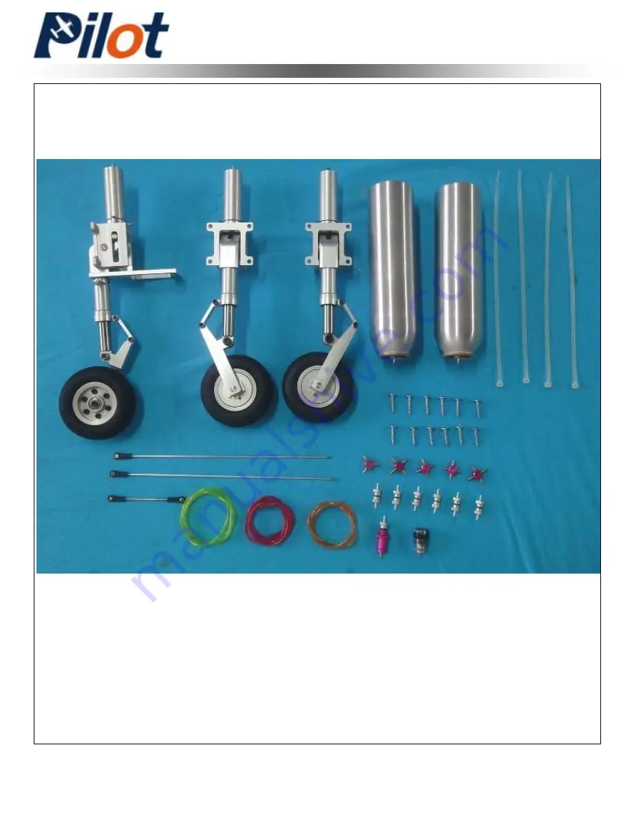
Retract Landing Gear Installation
Landing Gear Assembly
Page 1: ...Assembly Manual For Dolphin Jet...
Page 2: ...performance both the design and manufacturing have been taken care with the highest quality from any hardware covering wood and glue in the construction as well By optimal weight and reliable constru...
Page 3: ...ntrolled model It is impossible to determine for certain whether crash damage was the result of a radio system failure or pilot error even improper installation of our products Model airplane owner is...
Page 4: ...of a experienced person or airplane model clubs in assembly operation and maintenance to ensure quick and successful learning Fly only in proven model airfield that AMA Academy of Model Areonautics a...
Page 5: ...4 Retract Landing Gear Installation Landing Gear Assembly...
Page 6: ...Please note the connection from the retract valve to the cylinder Three cylinder orange tubes must connect to the orange tubes in the valve Three cylinder green tubes must connect to the green tubes i...
Page 7: ...tract valve fuel dot air pressure guage as the photo show Install the servo for brake and retract valve Fuel dot Air pressure guage Check valve Brake valve Retract valve 7 Install the nose retract gea...
Page 8: ...hole 8 Find the hole between the flap servo bay and the retract gear bay 10 This photo shows how the air tube go through the wing 9 Put the retract gear air tube from the flap servo bay to the root o...
Page 9: ...tract gear to the retract gear bay in the wing Fix the brake air tube as photos shows 12 Get the plastic landing gear cover 13 Cut the covering around the retract gear bay 14 Apply the 30 minutes epox...
Page 10: ...9 Landing Gear Assembly 15 Put the retract gear plastic cover into the retract gear bay 16 Apply the instant adhesive to glue the plastic cover to the wing...
Page 11: ...ver on the horns and locking plates 2 Trace around the locking plate with kinfe and cut off the cover below Then the pre cut slots appear 3 Scuff the horns with a piece of sand paper for good glue bon...
Page 12: ...horn into slot slightly and Mount the locking plate in place Wipe away excess epoxy with rubbing alcohol Servo Installation Wing Servo Assembly 1 Cut out the cover for servo location carefully Tape t...
Page 13: ...Find four sets of servo mounting plate Wing Servo Assembly 2 Lock the connector with the provided safety clip against vibration and loosened tension as shown 6 Glue two piece of wood to the servo mou...
Page 14: ...es Then screw four bolts to fix the servo to the servo mounting 8 Install servo arm Wing Servo Assembly 8 Install the servo arms facing toward the wing edge and adjust pushrod in proper length to keep...
Page 15: ...on the horns and locking plates 2 Trace around the locking plate with kinfe and cut off the cover below Then the pre cut slots appear 3 Scuff the horns with a piece of sand paper for good glue bond Th...
Page 16: ...with epoxy as shown 5 Slide the horns into slots slightly and Mount the locking plate in place Align the right and left sides before epoxy has cured Wipe away excess epoxy with rubbing alcohol Servo I...
Page 17: ...ng screws Face the brand toward the rear of fuse Elevator Servo Assembly 3 Install the servo arm with mounting screw and make it vertical with ground Adjust pushrod in proper length to keep the ailero...
Page 18: ...17 7 Repeat all the step above for the other stabilizer Elevator Servo Assembly 6 Install the stab with mounting bolts and washers...
Page 19: ...on the horns and locking plates 2 Trace around the locking plate with kinfe and cut off the cover below Then the pre cut slots appear 3 Scuff the horns with a piece of sand paper for good glue bond Th...
Page 20: ...horn into slot slightly and Mount the locking plate in place Wipe away excess epoxy with rubbing alcohol Servo Installation Rudder Servo Assembly 1 Cut out the cover for servo location carefully Tape...
Page 21: ...Find four sets of servo mounting plate Rudder Servo Assembly 2 Lock the connector with the provided safety clip against vibration and loosened tension as shown 6 Glue two piece of wood to the servo m...
Page 22: ...Then screw four bolts to fix the servo to the servo mounting 8 Install servo arm Rudder Servo Assembly 8 Install the servo arms facing toward the rudder edge and adjust pushrod in proper length to ke...
Page 23: ...the 30 minutes epoxy Note Must be sure the fin is vertical with the stabilizer Apply the 30 minutes epoxy Connect the rudder servo wire Glue the fin to the fuselage 2 There some small piece of coveri...
Page 24: ...23 Tail pipe Installation 1 Find the tail pipe fixing wood Fix to the tail of the fuselage by six bolt Not Include Fuselage Assembly 2 Fix the front of the tail pipe to the fuselage by four bolt...
Page 25: ...re and retract air tube go through the bottom of the fuel tank Show and the photos Fuselage Assembly There are precut hole on the fuselage for all the wire Show as the following photo Wing retract air...
Page 26: ...e note the gap should be 2cm as the photo shows Screw two set of wood to the 2nd floor understand the canopy Install the battery receiver as the photo shows Install the air tank flow air trap tank fue...
Page 27: ...Assembly The Dolphin jet come with the cockpit It does not preinstall in factory so you can put the pilot and instrument board in the cockpit Put the cockpit into the canopy Apply the instant adhesive...
Page 28: ...27 Navigate Light Assembly Note Navigate Light sell separately Not come with the plane You can Email Tony info pilot rc com to by it Total 7 LED light as shown below...
Page 29: ...battery 2 The LED light can work without radio control switch It will power on once you connect the power to the LED light 3 If you want to use the switch by radio control You must power on the receiv...
Page 30: ...29 Navigate Light Assembly Tail LED light Rudder LED light Nose landing gear LED light...
Page 31: ...30 Navigate Light Assembly Fuselage bottom LED light Nose landing gear LED light Fuselage top LED light...
Page 32: ...on Low rate Throttle Adjust idle full The First Flight set up Center Of Gravity The center of gravity is marked on the root of the wing Near to the wing tube as shown Your balance at the CG will dete...
Page 33: ...Have an experienced pilot fly it for you the first time if you have any doubts in your mind about the maiden flight Take a break after you first flight and let the adrenaline burned off by bragging t...