


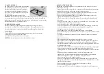


PARTS IDENTIFICATION
TECHNICAL DATA
Specification
Model No.
P29006
Rated Voltage & Frequency
220V-240V 50Hz
Power consumption
800W (IPX4)
Sutton House,
Berryhill Road,
Fenton
Stoke on Trent
Staffordshire,
ST4 2NL.
A. Base Of Main Unit
B. Water Tank
C1. Top Handle Shaft
C2. Middle Handle Shaft
C3. Bottom Handle Shaft
D. Power ON/OFF Indicator Light
E. Water Tank Alert Light
F. Foot Switch
G. Handle
H. Stopper
I. Cleaning Pad (see Page 10)
J. Carpet Glider
K. Shaft Adjustment Switch
L. Reset Button
A
F
K
G
B
D
E
L
H
C3
C2
C1
J
I
III
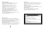
ASSEMBLING THE HANDLE AND SHAFT
Note: The three shaft sections (C1,C2 & C3) are different.
The handle section (C1) with its plastic locating lug at its base should be inserted into
the top of the shaft middle section
(C2). The locating lugs on the bottom of the handle section
(C1) will click into position.
Next locate this joined section of the shaft into the top of the bottom section (C3)
in the same way as previously described.
The assembled shaft should then be inserted into the main unit as shown in the two
photographs below.
Note: If the handle does not go right into its location, it is the wrong way round, please
do not force.
C3
C2
C1
C2
NOTE:
When inserting the Bottom Handle Shaft C3 in the main unit slide the shaft
down to locate the plastic lug (1) in the hole (2).
To remove press on the lug
(1) at the same time pulling the shaft upwards. Do NOT press on the cord cleat (3)
as it may break.
A
B
2
3
1
1
1
*
2