PICO PicoScope 2200 Series User Manual Download Page 13

PicoScope 2200 Series User's Guide

9

Copyright © 2008-2011 Pico Technology Limited. All rights reserved.

ps2200.en

3.5.3

Signal inputs

The PicoScope 2200 Series oscilloscopes have BNC oscilloscope connectors.  The
inputs have an impedance of 1 M , so they are compatible with all standard scope
probes including x10 attenuated types.

3.5.4

Compensating probes

We recommend that you compensate each oscilloscope probe before using it with your
PicoScope. Compensation instructions specific to the probe are included in the leaflet
supplied with the probe.

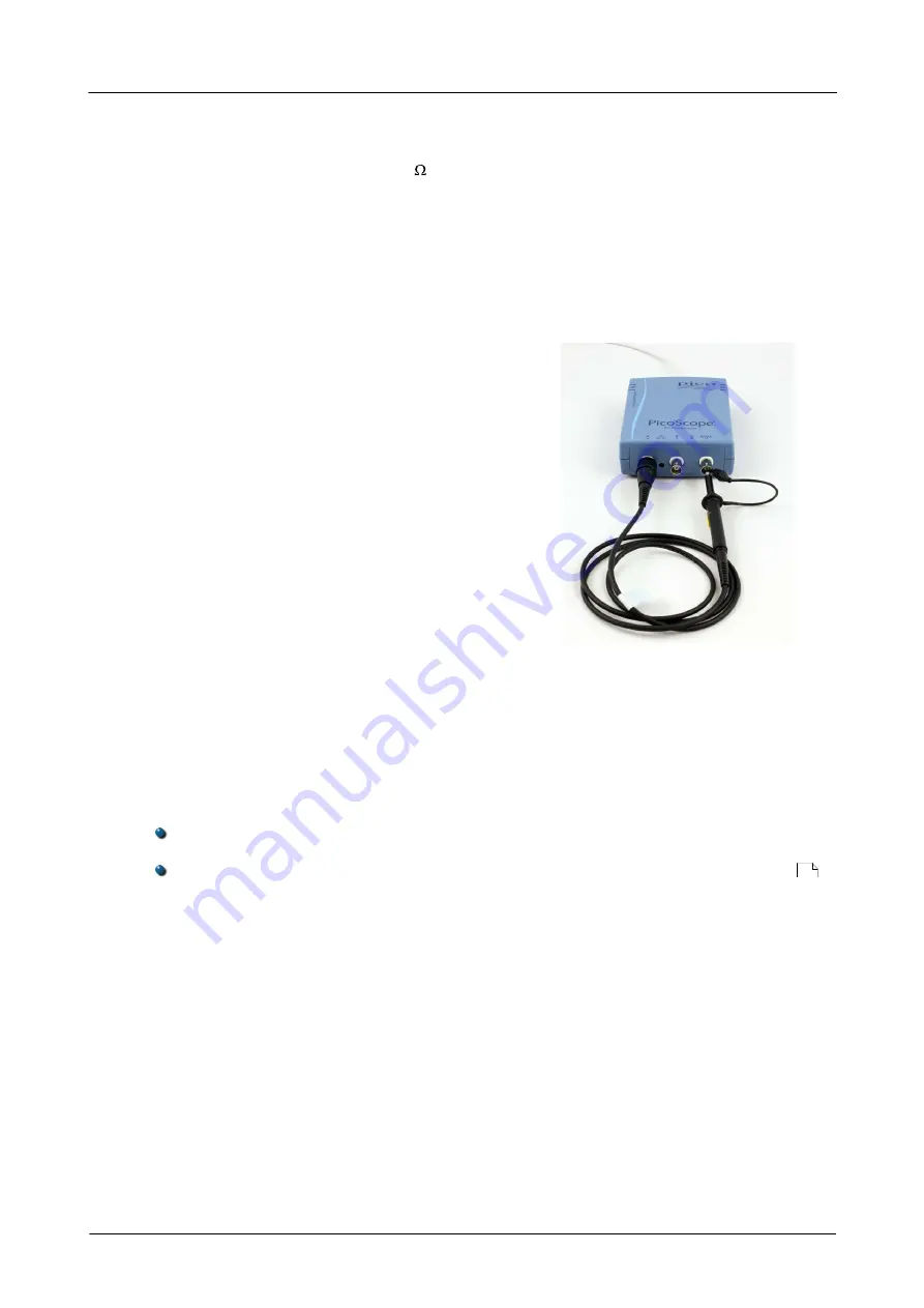
Connecting a probe for compensation

1. Connect your probe to the signal generator

output as shown on the right.

2. Run the PicoScope software.

3. Click the AWG button and set the AWG to

generate a 1 kHz 1 volt square wave.

4. Follow the compensation (or 'trimming')

instructions in the probe leaflet.

3.5.5

AWG connector

The 

AWG 

connector (labelled 

GEN 

or 

Signal Out 

on some oscilloscopes) on the front

panel carries the output of the oscilloscope's built-in signal generator, which can
generate a number of built-in waveforms, as well as arbitrary waveforms from a user-
defined table of data.

Instructions for use

If you are using the PicoScope 6 program, refer to the 

PicoS cope 6 U ser's G u ide

 for

information on how to configure the signal generator.
If you are writing your own software, refer to the relevant 

Program m er's G u ide

.

AWG output specifications

Refer to the 

PicoScope 2000 Series 

datasheet, available on our website.

3.5.6

EXT connector

The 

EXT 

(External) trigger input on some models can be used as a trigger source. The

trigger source is selected using the trigger drop-down menu in the PicoScope
software, or using a function call if you are writing your own software.

The 

EXT 

input uses dedicated circuitry with a software-configurable threshold to

detect a trigger signal. This has the advantage of freeing both analog channels for
viewing signals. However, if trigger timing accuracy and resolution are critical, we
recommend using the channel A or B input as the trigger source. These channels use
digital triggering, which is accurate to one sample period and has a vertical resolution
of 1 LSB.

1

Summary of Contents for PicoScope 2200 Series

Page 1: ...Copyright 2008 2011 Pico Technology Limited All rights reserved PicoScope 2200 Series User s Guide ps2200 en 1 PC Oscilloscopes...

Page 2: ......

Page 3: ...cence conditions 5 6 Trademarks 5 7 Warranty 5 8 Company details 6 3 Product information 6 1 Model selector 6 2 Pack contents 6 3 System requirements 7 4 Installation instructions 8 5 Connections 8 1...

Page 4: ......

Page 5: ...u can also call our specialists for technical support You can continue to use both of these services free of charge for the lifetime of the product Value for money Buying a PicoScope PC Oscilloscope m...

Page 6: ...n built in to equipment may cease to function if the equipment is used incorrectly This could cause damage to your computer or lead to injury to yourself and others Maximum input range The PicoScope 2...

Page 7: ...old Pico Technology Limited grants a licence to the person who installs this software subject to the conditions listed below Access The licensee agrees to allow access to this software only to persons...

Page 8: ...echnical support staff who will try to fix the problem within a reasonable time If you are still dissatisfied please return the product and software to your supplier within 14 days of purchase for a f...

Page 9: ...be free from defects in material and workmanship Pico Technology shall not be liable for a breach of the warranty if the defect has been caused by fair wear and tear wilful damage negligence abnormal...

Page 10: ...ng items Reorder code Quantity Description 1 PicoScope 2200 Series oscilloscope MI106 1 USB cable for connection to the USB port on your PC DI042 1 Software and Reference CD with PicoScope software dr...

Page 11: ...0 hertz noise signal in the oscilloscope window when you touch the probe tip with your finger Moving your PicoScope PC Oscilloscope to another USB port Windows XP SP2 When you first installed the osci...

Page 12: ...204 to 2205 A Input channel A B Input channel B C Signal generator output D LED shows when the oscilloscope is sampling data E USB port 3 5 2 Connector diagrams PicoScope 2206 to 2208 A Input channel...

Page 13: ...oscilloscope s built in signal generator which can generate a number of built in waveforms as well as arbitrary waveforms from a user defined table of data Instructions for use If you are using the P...

Page 14: ...hnology Limited All rights reserved ps2200 en 3 5 7 USB port Connect the oscilloscope s USB port to your PC s USB 2 0 port using the USB cable supplied The oscilloscope will work if connected to a USB...

Page 15: ...ose Properties then click the Hardware tab and the Device Manager button Driver A program that controls a piece of hardware The driver for the PicoScope 2000 Series PC Oscilloscopes is supplied in the...

Page 16: ...e draws the whole trace in a single operation The timebase is measured in units of time such as seconds per division There are ten divisions across the scope view so the total time across the width of...

Page 17: ...PicoScope 2200 Series User s Guide 13 Copyright 2008 2011 Pico Technology Limited All rights reserved ps2200 en 5 Appendix A Declarations of Conformity...

Page 18: ...Appendix A Declarations of Conformity 14 Copyright 2008 2011 Pico Technology Limited All rights reserved ps2200 en...

Page 19: ...nge maximum 2 Installation 7 L LED 8 M Mains voltages 2 O Operating system 6 Oscilloscope probe 9 compensating or trimming 9 P Pico Technical Support 5 PicoScope 2200 Series 1 PicoScope software 7 Pro...

Page 20: ......

Page 21: ...PicoScope 2200 Series User s Guide 17 Copyright 2008 2011 Pico Technology Limited All rights reserved ps2200 en...

Page 22: ...ouse Colmworth Business Park ST NEOTS Cambridgeshire PE19 8YP United Kingdom Tel 44 0 1480 396 395 Fax 44 0 1480 396 296 www picotech com Copyright 2008 2011 Pico Technology Limited All rights reserve...

Reviews: