background image

SECTION 3 - INSTALLATION & OPERATION 

Page 3.5

pickering

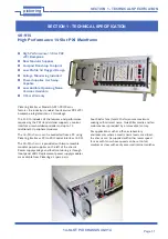
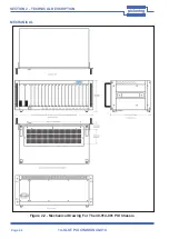
14-SLOT PXI CHASSIS 40-914

INSTALLING PXI MODULES

CAUTION

WARNING - DANGER OF ELECTRIC SHOCK

BEFORE REMOVING A  MODULE FROM THE CHASSIS ENSURE THAT ALL  

CONNECTIONS TO THE MODULE ARE REMOVED

Electrostatic discharge can damage the components on the module. To avoid such damage in handling 

the board, touch the anti-static bag to a metal part of the chassis before removing the board from the bag.

Ensure that there will be adequate ventilation for the module when fitted into the chassis.

The module should be installed in accordance with the following procedure:

1. 

Do not attempt to install, or remove, modules with the user connection attached. The UUT should be electrically 

and mechanically disconnected from the chassis.

2. 

Handle all PXI modules as you would any other static sensitive device. Ensure that the bag containing the PXI 

module is at the same voltage as the chassis by touching both at the same time. Store any modules being 

removed in a static protection bag.

3. 

Ensure that the system is turned OFF but still connected to mains so that it remains grounded.

4. 

Choose an appropriate slot in the rack.

5. 

Remove the blanking plate for the chosen slot.
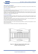
6.

  Ensure that the injector/ejector handle is in its downward position. Align the module with the module guides on  


the top and bottom of the slot.

CONNECTING THE SAFETY GROUND 

  WARNING 

THE 40-914 CHASSIS IS DESIGNED WITH A THREE-POSITION IEC CONNECTOR THAT CONNECTS THE 

GROUND LINE TO THE CHASSIS GROUND. TO MINIMIZE SHOCK HAZARD, MAKE SURE YOUR ELECTRICAL 

POWER OUTLET HAS AN APPROPRIATE EARTH SAFETY GROUND THAT IS CONNECTED WHENEVER 

YOU POWER UP THE CHASSIS. 

IF YOUR POWER OUTLET DOES NOT HAVE AN APPROPRIATE GROUND CONNECTION, YOU MUST 

CONNECT THE FACTORY WIRE SAFETY GROUND TO THE CHASSIS. TO CONNECT THE SAFETY GROUND, 

COMPLETE THE FOLLOWING STEPS:

1.   Connect a 16 AWG (1.3 mm) wire to a chassis grounding screw using a toothed grounding lug. The wire must 

have green insulation with a yellow stripe or must be non-insulated (bare). 

2.  Attach the opposite end of the wire to permanent earth ground using toothed washers or a toothed lug.

Summary of Contents for 40-914-101

Page 1: ...s underutilized and idle equipment along with credit for buybacks and trade ins Custom engineering so your equipment works exactly as you specify Critical and expedited services Leasing Rentals Demos...

Page 2: ...Page 1 14 SLOT PXI CHASSIS 40 914 pickering Issue 5 4 January 2014 User Manual 14 Slot PXI Chassis Model No 40 914 pickeringtest com pickering...

Page 3: ...SERVED No part of this publication may be reproduced transmitted transcribed translated or stored in any form or by any means without the written permission of Pickering Interfaces Technical details c...

Page 4: ...n be produced distributed used and recycled or disposed of in a safe and environmentally friendly manner Worldwide Technical Support and Product Information http www pickeringtest com Pickering Interf...

Page 5: ...Page iv 14 SLOT PXI CHASSIS 40 914 pickering THIS PAGE INTENTIONALLY BLANK...

Page 6: ...Section 2 Technical Description 2 1 Backplane 2 1 Power Supply 2 3 Mechanical 2 4 Section 3 Installation 3 1 Getting Started 3 1 Installing The Chassis 3 3 Fan Speed Setting 3 4 Connecting The Saftey...

Page 7: ...Page vi 14 SLOT PXI CHASSIS 40 914 pickering THIS PAGE INTENTIONALLY BLANK...

Page 8: ...ntrol interface or embedded controller and up to 13 additional 3U peripheral modules The 40 914 chassis can be controlled from a PC using Pickering Interfaces PCI to PXI Control Interface 41 921 The 4...

Page 9: ...ces Connection Solutions catalog for a full list of connector cabling options including drawings photos and specifications This is available in either print or as a download Alternatively our web site...

Page 10: ...r expansion slots which are used for system controller modules that are wider than one slot As defined in the PXI specification these slots allow the controller to expand to the left to prevent the co...

Page 11: ...0 914 Star Triggers PCI Arbitration and Clock Signals Local Bus Local Bus Local Bus Local Bus System Controller Slot 1 Star Trigger PeripheralSlot 2 Peripheral Slot 4 Peripheral Slot 3 Peripheral Slot...

Page 12: ...ule Users may insert or remove a redundant power supply from the system without interrupting the system operation provided the backplane load can be supplied from one power supply module However for s...

Page 13: ...Page 2 4 SECTION 2 TECHNICAL DESCRIPTION pickering 14 SLOT PXI CHASSIS 40 914 MECHANICAL Figure 2 2 Mechanical Drawing For The 40 914 001 PXI Chassis...

Page 14: ...220V alternative Installation CD includes electronic manuals and chassis ini files Environment The 40 914 chassis uses industrial standard mechanical components and high performance connector technolo...

Page 15: ...duct the main power connector must be disconnected Dangerous voltages may be present under certain conditions use extreme caution Explosive Atmosphere Do not operate the chassis in conditions where fl...

Page 16: ...on both sides and through the rear Cooling Considerations The area above and below the chassis should be kept clear to ensure the inlet and exhaust air paths are not obstructed The user should allow a...

Page 17: ...its back with PXI slots facing upwards to gain access to the underside 3 Remove the 5 crosshead screws securing the fan tray to the underside of the chassis as shown in Figure 3 2 4 Carefully lower t...

Page 18: ...any modules being removed in a static protection bag 3 Ensure that the system is turned OFF but still connected to mains so that it remains grounded 4 Choose an appropriate slot in the rack 5 Remove t...

Page 19: ...its downward position 7 Hold the handle whilst slowly sliding the module into the module guides until the handle catches on the injector ejector rail refer to Figure 3 5 8 Raise the injector ejector...

Page 20: ...required ini file from the download location to your PC using the following link http www pickeringtest info downloads drivers Chassis 2 Copy the files to any convenient location on your PC for examp...

Page 21: ...Page 3 8 SECTION 3 INSTALLATION OPERATION pickering 14 SLOT PXI CHASSIS 40 914 THIS PAGE INTENTIONALLY BLANK...

Page 22: ...Therefore when maintaining the chassis we suggest you always do so in a static free environment Please follow the standard handling procedures for static sensitive devices and wear a grounded wrist st...

Page 23: ...soap residue Do not use abrasive cleaning agents on any part of the chassis Cleaning the Fan Filters Remove the fan filters from the bottom of the chassis Clean the filters by washing them in a mild s...

Page 24: ...ensitive Semiconductor Devices Certain semiconductor devices used in this equipment are liable to damage due to static voltage Observe the following precautions when handling these devices in their un...

Page 25: ...Page 5 2 14 SLOT PXI CHASSIS 40 914 pickering THIS PAGE INTENTIONALLY BLANK...

Page 26: ...uipment Have surplus equipment taking up shelf space We ll give it a new home Learn more Visit us at artisantg com for more info on price quotes drivers technical specifications manuals and documentat...

Reviews: