


SECTION 2 - TECHNICAL DESCRIPTION
Page 2.1
pickering
14-SLOT PXI CHASSIS 40-914
SECTION 2 - TECHNICAL DESCRIPTION
BACKPLANE
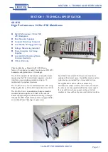
The 40-914 PXI chassis uses a 14-slot backplane which consists of 1 system slot and 13 peripheral slots (at 33 MHz)
with 20.32 mm (0.8 inch) board center-to-center spacing.
Key Features:
●
Compliant with PXI specification R2.1.
●
Two ATX sockets and screw terminals for +3.3V, +5V, ±12V DC output connection.
●
10-layer PCB for accurate impedance control.
●
ATX socket and screw terminals for DC output connection.
●
64-bit PCI bus on J1 and J2, support N-1 bus-mastering I/O slots (N: Slots).
●
System controller slot is located in slot 1.
●
Trigger controller slot is located in slot 2, providing individual triggers to all other peripherals.
Interoperability With CompactPCI
The 40-914 backplane is interoperable with PXI-compatible products and standard CompactPCI products. This is an
important feature, as many PXI-compatible systems may not require components that do not implement PXI-specific
features. For example, you may want to use a standard CompactPCI network interface card in a PXI chassis.
The signals on the P1 connector of the backplane meet the requirements of the CompactPCI specification for both
the peripheral and system modules.
The PXI-specific signals are located on P2 and are only found on the signals that are reserved or not used in
the CompactPCI 64-bit specification. Therefore, all modules that meet the requirements of the CompactPCI 64-bit
specification will function in the 40-914.
System Controller Slot
The System Controller slot is located in Slot 1 of the chassis as defined by the PXI specification. It has three
controller expansion slots, which are used for system controller modules that are wider than one slot. As defined
in the PXI specification, these slots allow the controller to expand to the left to prevent the controller from using up
peripheral slots.
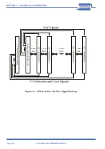
Star Trigger Slot
The Star Trigger (ST) slot is located at Slot 2. This slot has a dedicated trigger line between each peripheral slot
(see Figure 2.1). This slot is intended for modules with Star Trigger functionality that can provide individual triggers
to all other peripherals. However, if you do not require advanced trigger functionality, you can install any standard
peripheral module into this slot. Peripheral Slots - there are seven peripheral slots including the Star Trigger controller
slot. The Star Trigger Slot can also accept an external standard to replace the chassis reference clock, PXI_CLK10
supplied by the chassis.
Local Bus
The PXI backplane’s local bus is a daisy-chained bus that connects each peripheral slot with its adjacent peripheral
slots to the left and right, as shown in Figure 2.1.
For example, a given peripheral slot’s right local bus connects to the adjacent slot’s left local bus and so on. Each local
bus is 13 lines wide and can pass analog signals between cards or provide a high-speed side-band communication
path that does not affect the PXI bandwidth.
Local Bus signals may range from high-speed TTL signals to analog signals as high as 42V. Initialization software keys
adjacent boards to prohibit the use of incompatible boards. This software uses the configuration information specific
to each peripheral board to evaluate compatibility. This method is a flexible way to define local bus functionality that
is not limited by hardware keying.
Trigger Bus
The 40-914 includes the 8 trigger bus lines defined in the PXI standard to interconnect the system and peripheral
slots.