background image

Page 5.2

REED RELAY MODULE 40-110/115/120/125

pickering

SECTION 5 - CONNECTOR INFORMATION

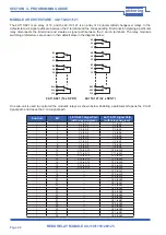
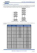
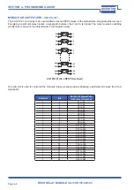
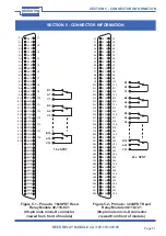
Figure 5.3 - Pinouts:  16xSPST Reed 

Relay Module 40-115-021 

(96-pin male micro-D connector 

viewed from front of module)

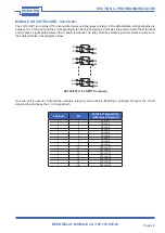
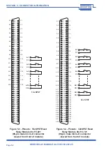
Figure 5.4 - Pinouts:  32xSPST Reed 

Relay Module 40-115-121 

(96-pin male micro-D connector 

viewed from front of module)

49
50
51
52
53
54
55
56
57
58
59
60
61
62
63
64
65
66
67
68
69
70
71
72
73
74
75
76
77
78
79
80
81
82
83
84
85
86
87
88
89
90
91
92
93
94
95
96

1
2
3
4
5
6
7
8
9

10

11

12
13
14
15
16
17
18
19
20
21
22
23
24
25
26
27
28
29
30
31
32
33
34
35
36
37
38
39
40
41
42
43
44
45
46
47
48

C1
-
C2
-
C3
-
C4
-
C5
-
C6
-
C7
-
C8
-
C9
-
C10
-
C11
-
C12
-
C13
-
C14
-
C15
-
C16
-
-
-
-
-
-
-
-
-
-
-
-
-
-
-
-
-

A1

-

A2

-

A3

-

A4

-

A5

-

A6

-

A7

-

A8

-

A9

-

A10

-

A11

-

A12

-

A13

-

A14

-

A15

-

A16

-
-
-
-
-
-
-
-
-
-
-
-
-
-
-
-
-

49
50
51
52
53
54
55
56
57
58
59
60
61
62
63
64
65
66
67
68
69
70
71
72
73
74
75
76
77
78
79
80
81
82
83
84
85
86
87
88
89
90
91
92
93
94
95
96

1
2
3
4
5
6
7
8
9

10

11

12
13
14
15
16
17
18
19
20
21
22
23
24
25
26
27
28
29
30
31
32
33
34
35
36
37
38
39
40
41
42
43
44
45
46
47
48

C1
-
C2
-
C3
-
C4
-
C5
-
C6
-
C7
-
C8
-
C9
-
C10
-
C11
-
C12
-
C13
-
C14
-
C15
-
C16
-
C17
C18
C19
C20
C21
C22
C23
C24
C25
C26
C27
C28
C29
C30
C31
C32

A1

-

A2

-

A3

-

A4

-

A5

-

A6

-

A7

-

A8

-

A9

-

A10

-

A11

-

A12

-

A13

-

A14

-

A15

-

A16

-

A17
A18
A19
A20
A21
A22
A23
A24
A25
A26
A27
A28
A29
A30
A31
A32

A16

C16

A3

C3

A2

C2

A1

C1

A31

C31

A4

C4

A3

C3

A2

C2

A1

C1

A32

C32

32 x SPST

16 x SPST

Summary of Contents for 40-110

Page 1: ...uy your excess underutilized and idle equipment along with credit for buybacks and trade ins Custom engineering so your equipment works exactly as you specify Critical and expedited services Leasing R...

Page 2: ...pickeringtest com Issue 5 5 January 2020 40 110 115 120 125 User Manual PXI Reed Relay Modules...

Page 3: ...TS RESERVED No part of this publication may be reproduced transmitted transcribed translated or stored in any form or by any means without the written permission of Pickering Interfaces Technical deta...

Page 4: ...s strives to fulfil all relevant environmental laws and regulations and reduce wastes and releases to the environment Pickering Interfaces aims to design and operate products in a way that protects th...

Page 5: ...rous voltages WARNING CAUTION An appropriate safety instruction should be followed or caution to a potential hazard exists Refer to the relevant instructions detailed within the product manual HEAVY I...

Page 6: ...Programming Guide 4 1 Programming Options For Pickering PXI Modules 4 1 Module Architecture 40 110 021 121 4 2 Module Architecture 40 115 021 121 4 3 Module Architecture 40 115 022 122 4 4 Module Arch...

Page 7: ...Page VI REED RELAY MODULE 40 110 115 120 125 pickering THIS PAGE INTENTIONALLY BLANK...

Page 8: ...y earth The host chassis must be correctly installed and be connected to mains or factory safety ground please refer to your chassis installation manual Diagram Showing Separation Between The Mains Ci...

Page 9: ...be isolated and disconnected from the power source and user I O signals refer to the Maintenance Section Appropriate manual handling procedures should be followed as dictated by the weight of the indi...

Page 10: ...IRST 3 Year Warranty The 40 110 115 range of switching modules are available in both Changeover SPDT and Normally Open SPST DPST configurations Connections are made via a front panel 96 pin male micro...

Page 11: ...Operating Conditions Operating Temperature Humidity Altitude 0 C to 55 C Up to 90 non condensing 5000m Storage and Transport Conditions Storage Temperature Humidity Altitude 20 C to 75 C Up to 90 non...

Page 12: ...nection accessories for the 40 110 series please refer to the 90 016D 96 pin micro D Connector Accessories data sheet where a complete list and documentation can be found for accessories or refer to t...

Page 13: ...ion Legacy and Hybrid Peripheral slots in a 3U PXI Express PXIe chassis Pickering Interfaces LXI or LXI USB Modular Chassis Chassis Selection Guide Standard PXI or hybrid PXIe Chassis from any Vendor...

Page 14: ...ckeringtest com software Signal Routing Software Our signal routing software Switch Path Manager automatically selects and energizes switch paths through Pickering switching systems Signal routing is...

Page 15: ...Page 1 6 REED RELAY MODULE 40 110 115 120 125 pickering SECTION 1 TECHNICAL SPECIFICATION THIS PAGE INTENTIONALLY BLANK...

Page 16: ...nding on the module type The relays are energised via control signals from relay driver U8 The relay driver is addressed by PCI bridge U1 to output the required signal Module configuration is determin...

Page 17: ...Page 2 2 REED RELAY MODULE 40 110 115 120 125 pickering SECTION 2 TECHNICAL DESCRIPTION THIS PAGE INTENTIONALLY BLANK...

Page 18: ...le s will connect with Ensure the chassis is not connected to the electrical supply 3 Ensure that the designated area for the chassis containing the module is of flat and solid construction to withsta...

Page 19: ...uate ventilation The module should be installed in accordance with the following procedure 1 Ensure that the system is turned OFF but still connected to mains so that it remains grounded 2 Choose an a...

Page 20: ...via the Start menu Start Menu Pickering Interfaces Ltd General Soft Front Panel A selector panel will appear listing all installed Pickering PCI PXI or LXI switch cards and resistor cards Click on the...

Page 21: ...Page 3 4 REED RELAY MODULE 40 110 115 120 125 pickering SECTION 3 INSTALLATION THIS PAGE INTENTIONALLY BLANK...

Page 22: ...ion on the installation and use of drivers and the programming of Pickering s products in various software environments please refer to the Software User Manual This is available as a download from ht...

Page 23: ...2 to A12 1 13 C13 to A13 C13 to A13 1 14 C14 to A14 C14 to A14 1 15 C15 to A15 C15 to A15 1 16 C16 to A16 C16 to A16 1 17 C17 to A17 1 18 C18 to A18 1 19 C19 to A19 1 20 C20 to A20 1 21 C21 to A21 1 2...

Page 24: ...C11 to A11 1 12 C12 to A12 C12 to A12 1 13 C13 to A13 C13 to A13 1 14 C14 to A14 C14 to A14 1 15 C15 to A15 C15 to A15 1 16 C16 to A16 C16 to A16 1 17 C17 to A17 1 18 C18 to A18 1 19 C19 to A19 1 20 C...

Page 25: ...1 C11 2 to A11 2 C11 1 to A11 1 C11 2 to A11 2 1 12 C12 1 to A12 1 C12 2 to A12 2 C12 1 to A12 1 C12 2 to A12 2 1 13 C13 1 to A13 1 C13 2 to A13 2 C13 1 to A13 1 C13 2 to A13 2 1 14 C14 1 to A14 1 C1...

Page 26: ...C4 to A4 1 5 C5 to A5 1 6 C6 to A6 1 7 C7 to A7 1 8 C8 to A8 1 9 C9 to A9 1 10 C10 to A10 1 11 C11 to A11 1 12 C12 to A12 1 13 C13 to A13 1 14 C14 to A14 1 15 C15 to A15 1 16 C16 to A16 The 40 120 021...

Page 27: ...C10 to A10 1 11 C11 to A11 1 12 C12 to A12 1 13 C13 to A13 1 14 C14 to A14 1 15 C15 to A15 1 16 C16 to A16 1 17 C17 to A17 1 18 C18 to A18 1 19 C19 to A19 1 20 C20 to A20 1 21 C21 to A21 1 22 C22 to A...

Page 28: ...s needed to hold the entire pattern ViUInt32 data 1 data 0 1 Sets lowest bit to 1 A1 C1 relay pipx40_setChannelPattern vi sub_unit data data 0 0x20 Sets 6th bit A6 C6 relay All other relays are set to...

Page 29: ...Page 4 8 REED RELAY MODULE 40 110 115 120 125 pickering SECTION 4 PROGRAMMING GUIDE THIS PAGE INTENTIONALLY BLANK...

Page 30: ...C11 C12 C13 C14 C15 C16 A1 B1 A2 B2 A3 B3 A4 B4 A5 B5 A6 B6 A7 B7 A8 B8 A9 B9 A10 B10 A11 B11 A12 B12 A13 B13 A14 B14 A15 B15 A16 B16 B1 A2 C2 B3 A4 C4 B5 A6 C6 B7 A8 C8 B9 A10 C10 B11 A12 C12 B13 A14...

Page 31: ...5 36 37 38 39 40 41 42 43 44 45 46 47 48 C1 C2 C3 C4 C5 C6 C7 C8 C9 C10 C11 C12 C13 C14 C15 C16 A1 A2 A3 A4 A5 A6 A7 A8 A9 A10 A11 A12 A13 A14 A15 A16 49 50 51 52 53 54 55 56 57 58 59 60 61 62 63 64 6...

Page 32: ...A10 2 A11 1 A11 2 A12 1 A12 2 A13 1 A13 2 A14 1 A14 2 A15 1 A15 2 A16 1 A16 2 49 50 51 52 53 54 55 56 57 58 59 60 61 62 63 64 65 66 67 68 69 70 71 72 73 74 75 76 77 78 79 80 81 82 83 84 85 86 87 88 89...

Page 33: ...3 74 75 76 77 78 79 80 81 82 83 84 85 86 87 88 89 90 91 92 93 94 95 96 1 2 3 4 5 6 7 8 9 10 11 12 13 14 15 16 17 18 19 20 21 22 23 24 25 26 27 28 29 30 31 32 33 34 35 36 37 38 39 40 41 42 43 44 45 46...

Page 34: ...5 6 7 8 9 10 11 12 13 14 15 16 17 18 19 20 21 22 23 24 25 26 27 28 29 30 31 32 33 34 35 36 37 38 39 40 41 42 43 44 45 46 47 48 C1 S1 C2 S2 C3 S3 C4 S4 C5 S5 C6 S6 C7 S7 C8 S8 C9 S9 C10 S10 C11 S11 C1...

Page 35: ...Page 5 6 REED RELAY MODULE 40 110 115 120 125 pickering SECTION 5 CONNECTOR INFORMATION THIS PAGE INTENTIONALLY BLANK...

Page 36: ...ny potential configuration problems Specific details of all installed Pickering switch cards are included All the installed Pickering switch cards should be listed in the Pilpxi information section if...

Page 37: ...REED RELAY MODULE 40 110 115 120 125 Page 6 2 pickering SECTION 6 TROUBLE SHOOTING THIS PAGE INTENTIONALLY BLANK...

Page 38: ...assis was manufactured the module may not be recognized in this case the chassis firmware may need upgrading This is a simple process which is described in the manual for the Modular LXI Chassis SWITC...

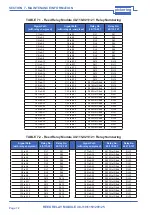
Page 39: ...LE 7 1 Reed Relay Module 40 110 021 121 Relay Numbering Signal Path with relay energised Signal Path with relay de energised Relay No 40 110 021 Relay No 40 110 121 C1 to A1 C1 to B1 RL1 RL1 C2 to A2...

Page 40: ...A17 2 RL17 Not Fitted RL17 C2 1 to A2 1 C2 2 to A2 2 RL2 RL2 C18 1 to A18 1 C18 2 to A18 2 RL18 Not Fitted RL18 C3 1 to A3 1 C3 2 to A3 2 RL3 RL3 RL19 Not Fitted RL19 C4 1 to A4 1 C4 2 to A4 2 RL4 RL...

Page 41: ...Fitted RL20 Not Fitted RL21 Not Fitted RL22 Not Fitted RL23 Not Fitted RL24 Not Fitted RL25 Not Fitted RL26 Not Fitted RL27 Not Fitted RL28 Not Fitted RL29 Not Fitted RL30 Not Fitted RL31 Not Fitted...

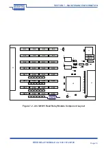
Page 42: ...3 C4 C1 C21 C24 C20 C14 C15 pickering R15 R4 C19 C16 J1 A B C A B C A B C A B C A B C A B C A B C A B C A B C A B C A B C A B C A B C A B C A B C A B C A B C A B C C23 U8 C18 C17 C11 C10 C8 C9 C7 C6 C...

Page 43: ...Page 7 6 REED RELAY MODULE 40 110 115 120 125 pickering SECTION 7 MAINTENANCE INFORMATION THIS PAGE INTENTIONALLY BLANK...

Page 44: ...uipment Have surplus equipment taking up shelf space We ll give it a new home Learn more Visit us at artisantg com for more info on price quotes drivers technical specifications manuals and documentat...

Reviews: