background image

6

Installation

6.1

Mounting the L-417.xx9211E1B

Overview

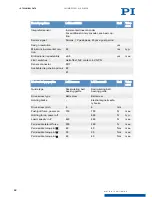
Figure 4: Mounting the L-417.xx9211E1B onto an underlying surface

Tools and Accessories

Screw set for mounting the L-417.xx9211E1B (p. 9)

Suitable screwdriver

Requirements

You have read and understood the 

general safety instructions (p. 7)

.

You have provided a suitable surface with the holes necessary for the 

screws and if

required, locating pins (p. 31)

.

The flatness of the surface is 

 2 μm.

For applications with large temperature changes: The surface should have the same or
similar thermal expansion properties as the L-417.xx9211E1B.

You have accounted for the space required to route cables without bending and
according to regulations.

DANGER

Risk of electric shock if the protective earth conductor is not connected!

If the protective earth conductor is missing or not properly connected, risk of dangerous
touch voltages on the L-417.xx9211E1B in the event of malfunction or failure of the system. If
there are touch voltages, touching the L-417.xx9211E1B leads to serious injuries or death by
electric shock.

Connect the L-417.xx9211E1B to a protective earth conductor before startup.

Do not remove the protective earth conductor during operation.

If the protective earth conductor has to be removed temporarily (e.g., for modifications),
reconnect the L-417.xx9211E1B to the protective earth conductor before restarting.

6  INSTALLATION

L417M0017EN 

 5/20/2019

14

M O T I O N   |   P O S I T I O N I N G

Summary of Contents for L-417.**9211E1B Series

Page 1: ...L417M0017EN 5 20 2019 User Manual L 417 XX9211E1B HIGH LOAD LINEAR STAGE M O T I O N P O S I T I O N I N G ...

Page 2: ...ope of Delivery 9 4 4 Overview 10 4 4 1 Base Body 10 4 4 2 Drive 11 4 4 3 Holding brake 11 4 4 4 Drag chain 11 4 4 5 Linear Encoder Connector 11 4 4 6 Purge Air System 12 5 Unpacking 13 6 Installation 14 6 1 Mounting the L 417 xx9211E1B 14 6 2 Connecting the L 417 xx9211E1B to the Protective Earth Conductor 15 6 3 Mounting the Load onto the L 417 xx9211E1B 17 6 4 Connecting the L 417 xx9211E1B 18 ...

Page 3: ...ssifications 30 12 4 Dimensions 31 13 Old Equipment Disposal 33 14 Appendix 34 14 1 Pin Assignment 34 14 1 1 Drive Connector 34 14 1 2 Motor encoder 34 14 1 3 Encoder connector 36 14 2 PTC temperature sensor 36 14 3 Commutation Encoder 37 14 4 Holding Brake Specifications 37 15 EU Declaration of Conformity 38 CONTENTS L417M0017EN 5 20 2019 3 M O T I O N P O S I T I O N I N G ...

Page 4: ...t With regard thereto Physik Instrumente PI GmbH Co KG reserves all rights The use of any text images and drawings is permitted only in part and only when indicating the source Original instructions First print 5 20 2019 Document number L417M0017en ASt Subject to change This manual is superseded by any new release The latest versions of the user manuals are available for download p 6 at www pi ws ...

Page 5: ...roduct example socket of the RS 232 interface Start Settings Menu path in the PC software example to open the menu the Start and Settings menus must be clicked successively POS Command line or a command from PI s General Command Set GCS example command to get the axis position Device S N Parameter name example parameter where the serial number is stor ed 5 Value that must be entered or selected vi...

Page 6: ...ing the access data You need the data storage device for the product to get the access data If a manual is missing or problems occur with downloading contact our customer service department p 26 Downloading Manuals 1 Open the website www pi ws 2 If the product was shipped with a data storage device Log into the website a Click Login b Enter the login data The login data is in the _Releasenews_ pdf...

Page 7: ...uilt according to state of the art technology and recognized safety standards Improper use of the L 417 xx9211E1B may result in personal injury and or damage to the L 417 xx9211E1B Use the L 417 xx9211E1B only for its intended purpose and if it is in perfect condition Read the user manual Eliminate any faults and malfunctions that are likely to affect safety immediately The operator is responsible...

Page 8: ... mm 4 L 417 099211E1B 204 mm 8 L 417 139211E1B 305 mm 12 L 417 179211E1B 407 mm 16 L 417 219211E1B 508 mm 20 L 417 259211E1B 610 mm 24 L 417 339211E1B 813 mm 32 4 2 Product Labeling 1 1 3 1 2 4 2 4 5 4 6 4 Figure 1 Product labeling on the L 417 xx9211E1B 1 Warning symbol Risk of crushing 2 Connector labels 3 Warning symbol Hot surface 4 Warning symbol Electrostatic sensitive device 5 Type plate 6 ...

Page 9: ...B with xx 05 09 13 17 L417B0014 Mounting kit for mounting the L 417 xx9211E1B and installation material consisting of 12 socket head screws ISO 4762 M6 30 2 dowel pins ISO 8734 4 m6 12 12 flat washers ISO 7092 D11 d6 4 h1 6 mm For L 417 xx9211E1B with xx 21 25 33 L417B0015 Mounting kit for mounting the L 417 xx9211E1B and installation material consisting of 20 socket head screws ISO 4762 M 6 30 2 ...

Page 10: ...e rotary motion of the drive to linear motion of the motion platform Reference Point Switch The reference point switch is a sensor whose fixed position serves as the reference point for incremental sensor signals Limit switches The limit switches are sensors at each end of the travel range that enable the electronics to abort motion in order to prevent the motion platform from colliding with the m...

Page 11: ...ngle of rotation This signal can be used by suitable electronics for commutating the motor 4 4 3 Holding brake The holding brake blocks the drivetrain at rest The holding brake is designed for holding only and is not suitable for continuous braking during operation The holding brake blocks in a zero voltage state 4 4 4 Drag chain The drag chain also energy chain or energy supply chain guides and p...

Page 12: ...ing strips that seal the openings on the side of the L 417 xx9211E1B s base body and therefore reduces the amount of dust that can penetrate Active dust protection The active dust protection consists of a purge air connector on the base body of the L 417 xx9211E1B which creates a slight overpressure in the L 417 xx9211E1B and therefore reduces the amount of dust that can penetrate 4 PRODUCT DESCRI...

Page 13: ...re damaged or missing contact our customer service department p 26 immediately 4 If the L 417 xx9211E1B was supplied with a carrying aid p 9 Use the carrying aid to transport the L 417 xx9211E1B to the intended place of use 5 If the L 417 xx9211E1B was supplied with ESD protective caps on the connectors Do not remove the ESD protective caps 6 Keep all packaging materials in case the product needs ...

Page 14: ...equired to route cables without bending and according to regulations DANGER Risk of electric shock if the protective earth conductor is not connected If the protective earth conductor is missing or not properly connected risk of dangerous touch voltages on the L 417 xx9211E1B in the event of malfunction or failure of the system If there are touch voltages touching the L 417 xx9211E1B leads to seri...

Page 15: ... Align the L 417 xx9211E1B on underlying surface so that the corresponding mounting holes in the L 417 xx9211E1B and underlying surface in line 3 Put the L 417 xx9211E1B onto the underlying surface so that the locating pins can be inserted into the corresponding locating holes with the L 417 xx9211E1B 4 If necessary Allow access to the mounting holes in the base body of the L 417 xx9211E1B Possibl...

Page 16: ...in the event of malfunction or failure of the system If there are touch voltages touching the L 417 xx9211E1B leads to serious injuries or death by electric shock Connect the L 417 xx9211E1B to a protective earth conductor before startup Do not remove the protective earth conductor during operation If the protective earth conductor has to be removed temporarily e g for modifications reconnect the ...

Page 17: ... pins as locating pins for aligning the load on the L 417 xx9211E1B Requirements You have read and understood the general safety instructions p 7 You have mounted the L 417 xx9211E1B on the surface p 14 properly The L 417 xx9211E1B is not connected to the electronics You have prepared the load so that it can be fixed to the mounting holes on the motion platform The distance between the center of g...

Page 18: ...with the following properties Pressure 2 to 6 bar 200 to 600 kPa purge air hose Outer diameter 4 mm air quality as stated in the specifications p 27 Requirements You have read and understood the general safety instructions p 7 You have read and understood the user manual for the electronics You have installed the electronics properly The electronics are switched off The L 417 xx9211E1B is connecte...

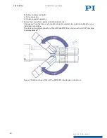
Page 19: ...drive and encoder connector carefully to a position suitable for your installation conditions The drive and encoder connector of the L 417 xx9211E1B can be turned up to 140 in steps of approximately 7 7 Figure 7 Rotation range of the L 417 xx9211E1B s drive sensor connectors 6 INSTALLATION L417M0017EN 5 20 2019 19 M O T I O N P O S I T I O N I N G ...
Page 20: ... shock Connect the L 417 xx9211E1B to a protective earth conductor before startup Do not remove the protective earth conductor during operation If the protective earth conductor has to be removed temporarily e g for modifications reconnect the L 417 xx9211E1B to the protective earth conductor before restarting CAUTION Risk of crushing by moving parts Risk of minor injuries from crushing between th...

Page 21: ...ion is indicated by a humming noise and can result from the following causes The load and or dynamics during operation differ considerably to the calibration settings The L 417 xx9211E1B is operated near to its resonant frequency If you notice oscillation stop the L 417 xx9211E1B immediately Starting and Operating the L 417 xx9211E1B 1 Start the electronics see the user manual for the electronics ...

Page 22: ...2 Perform a maintenance run over the entire travel range a Command the L 417 xx9211E1B to the end of a travel range and from there to the opposite end of the travel range see manual for the electronics b If necessary Command the L 417 xx9211E1B to a position where the load can be mounted onto the motion platform again and mount the load back onto the L 417 xx9211E1B p 17 8 2 Relubricating The L 41...

Page 23: ... 8 4 Moving the Motion Platform by Hand It can be necessary to move the motion platform manually to provide access to mounting holes for mounting screws in the base body of the positioner Requirements You have disconnected the L 417 xx9211E1B from the electronics Moving the Motion Platform by Hand 1 Apply the supply voltage p 37 to the holding brake connectors p 34 The holding brake is released 2 ...

Page 24: ...not exceeded Warped base body Mount the L 417 xx9211E1B onto an even sur face p 14 Increased wear due to small motion over a long period of time Perform a maintenance run p 22 Uncontrolled oscillation Large changes to the load or the alignment of the L 417 xx9211E1B Switch off the servo control system or the con troller immediately Check whether the servo control parameter set tings correspond to ...

Page 25: ...tion 1 Pay attention to the ambient conditions and classifications p 30 2 Pack the L 417 xx9211E1B in the original packaging 3 If the L 417 xx9211E1B is to be sent use a stable outer box 10 TRANSPORTATION L417M0017EN 5 20 2019 25 M O T I O N P O S I T I O N I N G ...

Page 26: ...n of the controller if applicable Version of the driver or the software if applicable Operating system on the PC if applicable If possible Take photographs or make videos of your system that can be sent to our customer service department if requested Customer service address Physik Instrumente PI GmbH Co KG Auf der Roemerstrasse 1 76228 Karlsruhe Germany service pi de www pi de 11 CUSTOMER SERVICE...

Page 27: ...l range 508 610 813 mm Pitch yaw 40 45 50 μrad max Straightness flat ness 9 10 12 μm max Velocity unloaded 300 300 300 mm s max Positioning accura cy uncalibrated 14 16 18 μm max Encoder options L 417 xxx232 basic option Unit Toler ance Integrated sensor Incremental rotary encoder Sensor signal A B quadrature RS 422 Sensor resolution 20000 Cts rev Design resolution 0 25 μm Minimum incremental mo t...

Page 28: ...0 E1 Mechanical properties L 417 xxxxxx L 417 xxxxxxB Unit Toler ance Guide type Recirculating ball bearing guide Recirculating ball bearing guide Drive screw type Ball screw Ball screw Holding brake Electromagnetic safe ty brake Drive screw pitch 5 5 mm Push pull force power on 700 700 N max Holding force power off 500 N typ Load capacity in Z 450 450 N max Permissible lateral force 250 250 N max...

Page 29: ...2 76 N m typ Nominal torque 0 7 N m typ Peak current RMS 10 9 A typ Nominal current RMS 2 73 A typ Torque constant RMS 0 32 N m A typ Resistance phase phase 5 22 Ω typ Inductance phase phase 9 7 mH typ Back EMF phase phase 20 4 V kRPM max Number of pole pairs 3 12 TECHNICAL DATA L417M0017EN 5 20 2019 29 M O T I O N P O S I T I O N I N G ...

Page 30: ... diame ter 4 mm Funnel type grease nipple for spindle lubri cation Limit switch connection M8 8 pin Purge air system Operating pressure 2 to 6 bar 200 to 600 kPa Relative humidity 70 Absolute humidity 35 g m3 Recommended controllers ACS modular controller Connecting cables are not in the scope of delivery and must be ordered separately 12 2 Maximum Ratings The L 417 xx9211E1B is designed for the f...

Page 31: ...m Note that the decimal places are separated by a comma in the drawings BASIS MODELL TRAVEL NOMINAL LIMITSWITCH TO LIMITSWITCH LSW HARDSTOP TO HARDSTOP HDS A B C D E D1 D2 E1 E2 E3 L 417 xxx2xxEx L 417 xxxx25Ex L 417 xxxxxxxx L 417 xxxxxxxxB L 417 xxxx11E1 L 417 xxxx12E1 L 417 xxxxxxE0 L 417 xxx2xx L 417 xxxx25E1 L 417 05xxxx 102 4 102 105 109 365 185 150 119 5 153 5 28 44 28 5 L 417 09xxxx 204 8 ...

Page 32: ... 4 x M6 150 Figure 9 Motion platform of the L 417 xx9211E1B Dimensions and mounting holes Dimensions in mm Note that the decimal places are separated by a comma in the drawings 12 TECHNICAL DATA L417M0017EN 5 20 2019 32 M O T I O N P O S I T I O N I N G ...

Page 33: ... order to fulfil the responsibility as the product manufacturer PI miCos undertakes environmentally correct disposal of all PI miCos equipment free of charge if it was made available to the market after August 13 2005 Any old PI miCos equipment can be sent free of charge to the following address PI miCos GmbH Freiburger Strasse 30 79427 Eschbach Germany info pimicos de www pi de 13 OLD EQUIPMENT D...

Page 34: ...ignal Function 1 U Phase 1 2 PE Protective earth 3 W Phase 3 4 V Phase 2 A BR Holding brake 24 V DC B BR Holding brake GND C nc Not connected D nc Not connected 14 1 2 Motor encoder 3 1 2 3 4 5 6 7 8 9 10 11 12 13 14 15 16 17 14 APPENDIX L417M0017EN 5 20 2019 34 M O T I O N P O S I T I O N I N G ...

Page 35: ...nv Output Sensor signal Z inverted 7 GND Ground 8 THERM Output Temperature sensor 9 THERM Output Temperature sensor 10 VCC Input Power supply 11 NC Not connected 12 NC Not connected 13 NC Not connected 14 NC Not connected 15 U Output Commutation track U 16 V Output Commutation track V 17 W Output Commutation track W 14 APPENDIX L417M0017EN 5 20 2019 35 M O T I O N P O S I T I O N I N G ...

Page 36: ...onnected C Outer shielding 14 2 PTC temperature sensor The L 417 xx9211E1B is equipped with a PTC temperature sensor to prevent the motor from overheating The electrical resistance of the PTC temperature sensor increases considerably into the critical temperature range The controller must cut the power supply to the motor switching threshold when the critical temperature is reached Temperature Ele...

Page 37: ... UV VW UW Figure 12 Motor phases top and signal output to the commutation tracks bottom 14 4 Holding Brake Specifications Parameters Value Supply voltage 24 V Power requirement 350 mA min Static braking torque 1 42 Nm Release brake delay 35 ms Brake delay 36 ms Linear brake offset 14 μm max 6 4 μm typical 14 APPENDIX L417M0017EN 5 20 2019 37 M O T I O N P O S I T I O N I N G ...

Page 38: ...with the following European directives Low Voltage Directive EMC Directive RoHS Directive The standards applied for certifying conformity are listed below Safety Low Voltage Directive EN 61010 1 EMC EN 61326 1 RoHS EN 50581 15 EU DECLARATION OF CONFORMITY L417M0017EN 5 20 2019 38 M O T I O N P O S I T I O N I N G ...

Page 39: ...measurement methods the resolution of the sensor system is specified Lateral Force Also lateral load capacity Maximum permissible force orthogonally to the positioning direction This value is valid directly for the motion platform and is reduced when the force acts above the platform Limit Switch Each limit switch sends its signal to the controller on a dedicated line The controller then interrupt...

Page 40: ... resolution separately Rotary encoder Impulses per screw rotation Linear encoder Smallest motion still detected by the sensor system Travel range The maximum possible travel range is limited by the length of the drive screw A possible gap between the limit switches determines the travel range L417M0017EN 5 20 2019 40 M O T I O N P O S I T I O N I N G ...

Reviews: