


B E W E G E N | P O S I T I O N I E R E N
MS242EK 2.1.0 10/2019. 2.0
Page 4 of 8
Tools and accessories
▪
▪
Suitable cable, e.g.,
▪
▪
RS-232 null modem cable
▪
▪
USB cable
▪
▪
Straight-through or crossover network
cable
Connecting to the USB interface
X
Connect the USB cable to the USB socket
on the electronics and the USB interface on
the PC.
Connecting to the RS-232 interface
1.
Connect the RS-232 null modem cable to
the RS-232 connector on the electronics
and a vacant RS-232 interface on the PC.
2.
Use the integrated screws to secure the
connection against accidental disconnec-
tion.
Connecting to a network
X
Connect the network cable to the RJ-45
socket on the electronics and the network
access point or PC.
Connecting the Power Adapter to the
Electronics
Requirements
✔
The power cord is
not
connected to the
power socket.
Tools and accessories
▪
▪
Power adapter supplied or correctly rated
power adapter
▪
▪
If necessary: Cable adapter supplied for the
power adapter connector or correctly rated
cable adapter
▪
▪
Power cord supplied or correctly rated
power cord
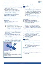
Connecting the power adapter to the electro-
nics using the cable adapter
1.
Connect the cable adapter (
3
) to the power
adapter connector (
4
) of the electronics.
2.
Connect the barrel connector on the cable
adapter (
3
) to the barrel connector socket
on the power adapter (
1
).
3.
Connect the power cord to the power
adapter.
Electronics with M8 panel plug
Electronics with Sub-D 2W2C panel plug
1
Barrel connector of the power adapter
2
Barrel connector on the adapter
3
Connector (f) on the adapter
4
Power adapter connector (m)
Connecting the power adapter to the electro-
nics without cable adapter
X
Connect the power adapter to the power
adapter connector on the electronics.
X
Connect the power cord to the power
adapter.
M O T I O N | P O S I T I O N I N G