


MS242EK 2.1.0 10/2019. 2.0
Page 3 of 8
If the electronics are to be used as a benchtop
device:
X
Make sure that the electronics are standing
safely and securely.
If the electronics are to be mounted:
1.
Bore the required holes into the surface.
2.
Insert a suitably sized screw into each
recess to fix the electronics.
Connecting the Electronics to the
Protective Earth Conductor
If a protective earth connector is available on
the electronics, it must be connected to the
protective earth conductor.
Requirements
✔
The electronics are switched off.
Tools and Accessories
▪
▪
Suitable protective earth conductor:
▪
▪
Cable cross section ≥0.75 mm²
▪
▪
Contact resistance < 0.1 ohm at 25 A at
all connection points relevant for atta-
ching the protective earth conductor
▪
▪
Mounting hardware for the protective
earth conductor; is on the protective earth
connector on delivery of the electronics
▪
▪
Suitable wrench
Connecting the protective earth conductor
1.
Fasten a suitable cable lug to the protective
earth conductor.
2.
Attach the cable lug of the protective earth
conductor to the protective earth connec-
tor using the mounting hardware supplied.
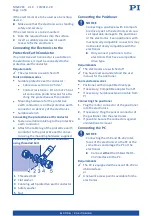
Connecting the protective earth conductor
using threaded bolt
1
Threaded bolt
2
Flat washer
3
Cable lug with protective earth conductor
4
Safety washer
5
Nut
Connecting the Positioner
NOTICE
Connecting a positioner with incompati-
ble drive type to the electronics can cau-
se irreparable damage to the positioner
or the electronics. Even positioners with
mechanically compatible connectors may
not be electrically compatible with the
electronics.
X
Only connect positioners to the
electronics that have a compatible
drive type.
Requirements
✔
The electronics are switched off.
✔
You have read and understood the user
manual for the positioner.
Tools and accessories
▪
▪
Positioner with compatible drive type
▪
▪
If necessary: Compatible adapter from PI
▪
▪
If necessary: Suitable extension cable from
PI
Connecting the positioner
1.
Plug the motor connector of the positioner
into the electronics.
2.
If necessary: Plug the sensor connector of
the positioner into the electronics.
3.
If possible: Secure the connectors against
unintentional removal.
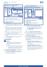
Connecting the PC
NOTICE
Connecting the USB and RS-232 inter-
faces of the electronics to the PC at the
same time can damage the PC or the
electronics.
X
Connect
either
the USB
or
the RS-
232 interface to the PC.
Requirements
✔
The PC is equipped with a vacant RS-232 or
USB interface.
or
✔
A network access point is available for the
electronics.
M O T I O N | P O S I T I O N I N G