Phytec USB-CAM-003H Manual Download Page 28

USB-CAM-003H / 103H / 004H / 104H / 051H / 151H / 052H / 152H 


2.5


Starting Up the Camera with the Demo Program 

2.5.1


The First Live Image 

After you have established the necessary connections, installed the 
driver and the demo software and mounted a lens following the 
instructions in the previous sections, you can now start up the camera 
and display a live image on the screen. 
 
You can also use the program 

amcap.exe

 by Microsoft™  included on 

the CD SO-221 for the display of a live image.  
To use all of the cameras’ features, we nevertheless recommend the 
PHYTEC Vision Demo program as described in the following.  
 
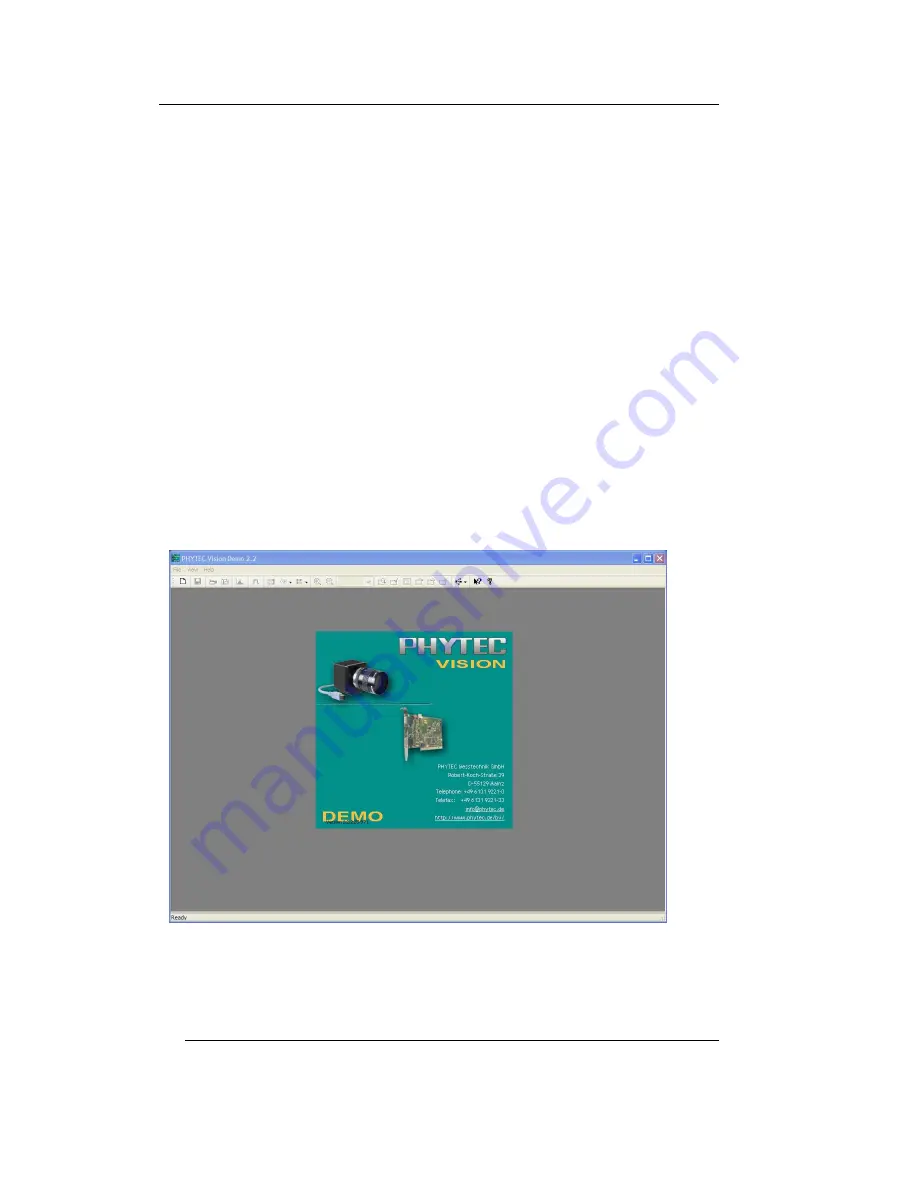
Start the „PHYTEC Vision Demo“ from the list you chose during the 
installation. 


The program surface will appear (

Figure 20

).  


Figure 20:  The Program „PHYTEC Vision Demo“ 


Choose then the correct image source.  


26


©

 PHYTEC Messtechnik GmbH 2011     L-740e_0 

Summary of Contents for USB-CAM-003H

Page 1: ...USB CAM Series USB CAM 003H USB CAM 103H USB CAM 004H USB CAM 104H USB CAM 051H USB CAM 151H USB CAM 052H USB CAM 152H Manual Edition January 2011 A product of a PHYTEC Technology Holding company...

Page 2: ...HYTEC Messtechnik GmbH offers no guarantee nor accepts any liability for damages arising from the improper usage or improper installation of the hardware or software PHYTEC Messtechnik GmbH further re...

Page 3: ...ogram 2 5 1 26 The First Live Image 2 5 2 28 Select resolution 2 5 3 30 Problem Solving 2 5 4 31 Adjusting Camera Settings 3 37 The Camera in Detail 3 1 37 Camera Connections 3 1 1 37 USB Interface 3...

Page 4: ...Warning Figure 13 19 Driver Installation Step 3 Figure 14 20 Lens Assembly C Mount Figure 15 21 Flange Back Distances and Mounting of C Mount Top CS Mount Bottom Lenses Figure 16 24 Title Menu of the...

Page 5: ...pixel models 42 Figure 36 virtual sensor size at different resolutions 42 Figure 37 45 Mounting Plate Figure 38 46 Attachment of the Mounting Plate Figure 39 46 Mounting Options of the USB CAM Figure...

Page 6: ...material designed to be compatible with the camera from PHYTEC Figure 1 USB Connecting Cable USB Connecting Cable 1 5 m Order number WK184 Hint Please note that the full data rate is specified for a...

Page 7: ...era and USB bus This will usually be the USB interface host controller of your computer PHYTEC provides therefore a cable You can use any other cable alternatively if they comply with the USB 2 0 stan...

Page 8: ...50 fps Order number AK087 AK089 AK088 AK090 Resolution 2592 x 1944 5 MPix 2048 x 1536 3 1MPix 1600 x 1200 2MPix 1280 x 960 1 2MPix 1024 x 768 0 8MPix 640 x 480 VGA Model USB CAM 051H USB CAM 151H USB...

Page 9: ...ing and wrong storage Do not try to disassemble the camera To avoid electric shocks do not remove neither screws nor the case There are no components in the camera that need user maintenance Maintenan...

Page 10: ...ed 1 5 Declaration of Conformity The cameras meets the EC directive 2004 108 EG for a digital device of class B They have been tested and thus conform to EN 55016 2 3 2006 EN 61000 6 3 2007 EN 61000 4...

Page 11: ...the camera That bus transmitts the video data the control data and the supply voltage for the camera Figure 2 Rear view without trigger The USB CAM 103H 104H 151H and 152H are equipped with a BNC sock...

Page 12: ...TEC SDK DirectX wrapper can be used It allows for a very convenient access to all features of the USB CAMs without the programmer having to become acquainted with the complexity of DirectX The SDK inc...

Page 13: ...ction 2 2 describes the installation of the software for all hardware variants 2 1 Hardware Installation on a PC 2 1 1 The USB Connection Check first if your computer is already equipped with a USB in...

Page 14: ...the camera Figure 7 Figure 7 USB Connecting Cable Type A Type Mini B Depending on the desired length of the cable you can use one of these USB cables for the connection USB connecting cable 1 5 m Ord...

Page 15: ...s To put the camera into operation simply plug one end of the USB cable Type Mini B into the socket on the back of the camera and the other end into the USB Connector on your PC Further connections ar...

Page 16: ...b you must usually use an external power supply for the hub otherwise it can happen that the USB port can only be loaded with about 100mA processor Pentium IV 2GHz 512 MB RAM or higher Graphics adapto...

Page 17: ...tomatically bringing up the title menu shown in Figure 8 If the CD doesn t start automatically open the content folder of the CD from your desktop or using Windows Explorer and double click on SO 221...

Page 18: ...will be taken to the installation menu for the PHYTEC USB Camera Install 32Bit Driver Figure 9 and click on Next To install the 64Bit driver please select the Install 64Bit Driver Figure 9 Installati...

Page 19: ...should already be selected If no selection appears check to see if the camera is connected correctly and ready for operation This is required before the driver can be installed Click on Next or Weiter...

Page 20: ...USB CAM 003H 103H 004H 104H 051H 151H 052H 152H Figure 11 Driver Installation Step 2 Figure 12 Driver Installation Compatibility Warning 18 PHYTEC Messtechnik GmbH 2011 L 740e_0...

Page 21: ...several different type cameras of the PHYTEC USB series on the same computer you have to perform the installation procedure for each camera After the installation procedure has been performed on a co...

Page 22: ...e a few recommendations for selecting an appropriate lens in section 3 2 The following paragraphs provide instructions on the connection of a lens The USB CAM series works with C resp CS Mount lenses...

Page 23: ...es shown in Figure 15 illustrate the difference Figure 15 Flange Back Distances and Mounting of C Mount Top CS Mount Bottom Lenses In reality the mechanics of the lens and the cameras can vary slightl...

Page 24: ...ith the imaging system it should only be done if absolutely necessary If the picture is out of focus in all of the lens ranges please check to see if you have a C Mount lens use adapter ring or a CS M...

Page 25: ...meets the hardware requirements and is equipped with this software To install the driver software for the USB camera proceed in the following manner Caution The DirectX driver must be installed prior...

Page 26: ...Title Menu of the Vision Tools CD Click on USBe CAM You will be taken to the installation menu for the PHYTEC USB cameras Select PHYTEC DEMO Figure 17 and click on Next Figure 17 Installation Menu for...

Page 27: ...he USB cameras will appear Figure 18 Figure 18 Demo Installation Step 1 Click on Next Figure 19 Installation Completed Step 4 After successfully completing the installation finish the procedure with F...

Page 28: ...camera and display a live image on the screen You can also use the program amcap exe by Microsoft included on the CD SO 221 for the display of a live image To use all of the cameras features we nevert...

Page 29: ...igure 21 Figure 21 PHYTEC Vision Demo Select Device A live image will appear in the program window Figure 22 In case the live image does not appear choose the entry Live under Device Figure 22 PHYTEC...

Page 30: ...effects and problems that may arise from sub sampling of fine structures you should choose the native resolution slightly higher than the calculated Remember that a too high resolution produces a hig...

Page 31: ...bined The camera is more light sensitive Use the binning mode if you need a higher light sensitivity of the camera Sensor format epending on the method of resolution reduction changed the virtual sens...

Page 32: ...s 2 5 3 Problem Solving Check the following points if the live picture is poor or doesn t appear No Video Device is recognized Is the camera connected to the computer correctly Is the software driver...

Page 33: ...ing Adjust the picture frequency to the frequency of the artificial lighting Use either a high exposure time or use frequency independent lighting Note Occurring interference at 30 Hz is not a defect...

Page 34: ...ou can make basic settings for the image format and color depth Furthermore you can see the serial number of the camera and you can also set the picture refresh rate Figure 25 Camera Setting Device Se...

Page 35: ...In order to make the settings manually remove the Auto check from behind the desired parameter and set the desired value with the sliding control Please note that depending on the camera model not all...

Page 36: ...e timer This allows the general lighting impression to be adjusted to the application Figure 27 Camera Setting Properties Exposure Properties Special Figure 28 In this dialog you can activate the exte...

Page 37: ...he Offset u can individually set the center of the image Properties Partial Scan Figure 29F nicht gefunden werden This dialog is only 152H are available In this dialog you can select the binning So yo...

Page 38: ...her possible Settings of the PHYTEC Vision Demo Further functions of the PHYTEC Vision Demo Recording an AVI file Storing of an individual image BMP JPG Recording of an image sequence Setting and disp...

Page 39: ...rt Make sure that the used USB interface can provide enough power for the camera The USB 2 0 interface can be loaded associated with standard loaded up to 500 mA If you using a USB hub you usually nee...

Page 40: ...t Open Drain 24V 3 Trigger_In In Trigger Input GND 4 Trigger_In In Trigger Input Signal 3 3V 12V Figure 32 Trigger Connector 3 1 2 1 Trigger functions free running operation Depending on the selected...

Page 41: ...smission undefined conditions may happen during the picture recording Figure 33 Waveform Trigger To test the trigger functions please use the PHYTEC demo program section 2 4 3 1 2 2 Digital Output To...

Page 42: ...d Sample code for addressing the digital output private VCDSimpleProperty VCDProp private void Form1_Load object sender EventArgs e icImagingControl1 Device DEVICE NAME Abfrage der Kamera Einstellunge...

Page 43: ...ength depends on the size of the sensor chip the distance from the object and the focal length of the lens being used The screen window should be optimized so that the object being captured is always...

Page 44: ...mm 1280 x 960 1 4 5 2 1mm 2 8mm 1024 x 768 1 5 5 1 7mm 2 3mm 640 x 480 1 9 1 1mm 1 4mm Binning Mode 1280 x 960 1 2 5 4 3mm 5 7mm 640 x 480 1 2 5 4 3mm 5 7mm Figure 35 virtual sensor sizes 5M pixel mod...

Page 45: ...engths can be found in our catalog and on our web site Please ask us about other available focal lengths Resolution How good will the picture resolution be for a given focal length This depends on the...

Page 46: ...which the picture can be rendered in focus The M O D value is given in the lens data An input M O D 0 3 m means that the object has to be at least 30 cm from the lens Often the camera has to be brough...

Page 47: ...ecessary to prevent noise in the picture In industrial applications it usually makes sense to be able to lock the selected aperture setting For this purpose some lenses are equipped with fixing screws...

Page 48: ...le and can be easily adapted to a given application Note If necessary you can also attach the camera directly without using the mounting plate on your body by using the M3 thread in the camera body Pa...

Page 49: ...e a special requirement profile we recommend lenses from Schneider Kreuznach We will be happy to advise you on the selection of an appropriate lens 3 4 2 Lighting With image processing applications th...

Page 50: ...bject such as print dirt color in this case a color stable lighting is recommended or mounted parts attendance moni monitor There are different variations of this method Problems that may occur with t...

Page 51: ...2011 L 740e_0 49 ler Verweisquelle konnte nicht gefunden werden 7 The light field lighting leaves the ranges of interest dark e g a drill hole in a workpiece The dark field lighting functions in the o...

Page 52: ...lt to discern contrast problems If the background isn t too dark you can measure the object s cast shadow instead of the object edge n Figure 42 The Shadow Projection e g from a laser This is an expan...

Page 53: ...is projected at a known angle toward the object The camera is positioned perpendicular to the object The picture therefore contains two parallel lines that are a distance d from one another This dista...

Page 54: ...on the surface of the object With the silhouette projection the object is placed before a luminescent plate It is a diffuse lighting surface that lights the object from below The camera is pointed at...

Page 55: ...listed in section Fehler Verweisquelle d for typical automation the subsequent be instances where a mixture of both requirement profiles is needed konnte nicht gefunden werden In the following paragr...

Page 56: ...the highest gray value dynamic Sharpness Adjust the sharpness of the picture according to the visual impression that it makes Be aware that too high of a Sharpness setting will also show noise more c...

Page 57: ...ge If the lighting conditions between the various image portions are considerably different then you can compensate for this effect with another method of measurement This enables you to limit the mea...

Page 58: ...variations we rarely notice even relatively major color variations in light in the course of a day The camera can also adapt to color variations with the help of the Automatic White Balance If only t...

Page 59: ...htness as low as possible This guarantees the highest gray value dynamic Sharpness Adjust the image sharpness to the level you desire In automated applications you should try to set the sharpness to t...

Page 60: ...establish the data exchange between the devices With DirectShow part of the Windows SDK the PHYTEC cameras use a protocol that defines the transmission of uncompressed image data streams as well as th...

Page 61: ...rresponding programming description is available in the DirectX SDK from Microsoft The functions made available by the PHYTEC USB CAM are described in section Verweisquelle konnte nicht gefunden werde...

Page 62: ...USB CAM 003H 103H 004H 104H 051H 151H 052H 152H 60 PHYTEC Messtechnik GmbH 2011 L 740e_0 programmer The WDMIAT reduces the complexity of DirectX and makes a logically simple interface available to the...

Page 63: ...the layer of a WDM Stream Class driver The communication between this typ application software is defined by the standard called DirectX DirectShow There are three typical ways of accessing Programme...

Page 64: ...limited tool It consists only of the executable program graphedt exe and is therefore easy to locate in the DDK SDK Kit No special installation is required graphedt exe can be started easily from any...

Page 65: ...s also considered a filter of this type and is located in the folder Video Capture Sources The filter parameters i e the camera settings can be modified by right clicking on the name of the filter in...

Page 66: ...USB CAM 003H 103H 004H 104H 051H 151H 052H 152H 64 PHYTEC Messtechnik GmbH 2011 L 740e_0...

Page 67: ...Dyn nge amic Ra 8 bit Shutter Global Li ity ght sensitiv 4 8 V lux sec Interface USB 2 0 High Speed Exp time 1 4 s osure 10 000 s to 1 Gain 0 dB to 18 dB White Balance B bis 6 dB 6 d Power supply 4 5...

Page 68: ...Raw Lens Holder S t C C Moun fps 6 fps to 52 fps Dyn ge amic Ran 8 bit Shutter Rolling Light se sitivity lux n 1 4 V sec Interface 0 High Speed USB 2 Exposure time 1 10 000 s to 30 s Gain to 1 0 dB 8...

Page 69: ...x 480 640 x 480 320 x 240 1 3 1 3 5 1 7 60 90 150 4 8 V lux sec 4 8 V lux sec 4 8 V lux sec Models USB CAM 051H USB CAM 151H USB CAM 052H USB CAM 152H Resolution Format fps Sensitivity Readout window...

Page 70: ...USB CAM 003H 103H 004H 104H 051H 151H 052H 152H 68 PHYTEC Messtechnik GmbH 2011 L 740e_0 6 Dimensions Figure 46 Dimensions without trigger...

Page 71: ...Dimensions Figure 47 Dimensions with trigger PHYTEC Messtechnik GmbH 2011 L 740e_0 69...

Page 72: ...03H 103H 004H 104H 051 151 052 152 Dokument Number L 740e_0 January 2011 How would you improve this manual Did you find any mistakes in this manual Page Submitted by Customer number Name Company Addre...

Reviews: