


EDF ENR PWT
33,
Rue
Saint
Honoré
‐
Z.I.
Champfleuri
38300
Bourgoin
Jallieu
‐
France
Tel
:
33
4
74
93
80
20
‐
Fax
:
33
4
74
93
80
40
EDF
ENR
PWT
Société
par
actions
simplifiée
à
associé
unique
–
au
capital
de
37
505
000
€
‐
N°
513
281
972
RCS
NANTERRE
Siège
social
:
100
Esplanade
du
Général
de
Gaulle
–
Cœur
Défense
–
Tour
B
92932
Paris
La
Défense
cedex
.
D07-P0
6-01
GB
Ind
ice
1
Date
:
3
-01-13
7
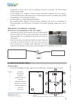
Cables and connectors
The mounting design must be certified by a registered professional engineer. The mounting design and
procedures shall comply with local electrical and building codes.
The module is considered to be in compliance with UL 1703 only when the module is mounted in the
manner specified by the mounting instructions below.
Mounting hardware is not provided by EDF ENR PWT.
EDF ENR PWT modules can be mounted to a support structure by several approved methods, either using
the mounting holes located on the back frame (see Example A), or by means of clamps (see Example B).
For other installation hardware, please contact your local representative for further information. Failure to
use a recognized installation method will void EDF ENR PWT warranty.
Only the bolting method has been qualified by all major North-American certification bodies (CSA, and
Intertek) during testing and listing of EDF ENR PWT modules according to UL1703 standard. For
inlay-systems or other installation hardware, please contact your local representative for further information.
Alternative mounting methods qualified internally by EDF ENR PWT are described in Annex C.
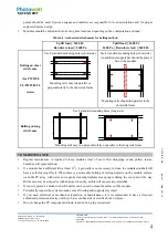
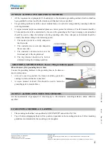
Example A:
Example B:
Bolting (INTERTEK and CSA qualified)
Clamping on (INTERTEK qualified)
Use appropriate corrosion-proof fastening materials. All mounting hardware (bolt/spring washer/flat
washer/nut) should be made with stainless steel M6 size for bolting method (A), and M8 size for clamping
method (B).
Use a torque wrench for installation. The above figure shows methods of fastening module to support
structure. Tightening torques should respectively be within 4~6 Nm and 10~17 Nm for M6x1 (Example A)
and M8x1.5 (Example B) coarse thread bolts, depending on bolt class. Different recommendations from
specific clamping hardware suppliers should prevail.
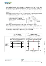
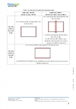
EDF ENR PWT modules can be installed in either landscape or portrait position, refer to the detailed
instructions (see table 6-1) for further guidance. Note that further countermeasures such the use of
additional support bars should be considered in heavy snow areas (> 2400 Pa), to avoid damage by the snow
accumulating in the lowest row of modules.
When the addition of a support bar is recommended to enhance mechanical stability and module long term
performance reliability, material of suitable resistance should be selected. EDF ENR PWT recommends a
minimum thickness of 50mm for the bar. The support bar centerline should be positioned within 100 mm of
the side frame centerline (slight shift may be necessary to access module grounding hole).
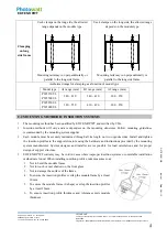
6.1 MOUNTING METHOD: BOLTING
Modules should be bolted to support structures through mounting holes located in the frame's back flanges
only. Do not drill additional holes or modify the module frame. Doing so will void the warranty.
Each module must be securely fastened at a minimum of 4 points on two opposite sides, using the most
inner mounting holes. If additional wind loads are anticipated for this installation, additional mounting


