

EDF ENR PWT
33,
Rue
Saint
Honoré
‐
Z.I.
Champfleuri
38300
Bourgoin
Jallieu
‐
France
Tel
:
33
4
74
93
80
20
‐
Fax
:
33
4
74
93
80
40
EDF
ENR
PWT
Société
par
actions
simplifiée
à
associé
unique
–
au
capital
de
37
505
000
€
‐
N°
513
281
972
RCS
NANTERRE
Siège
social
:
100
Esplanade
du
Général
de
Gaulle
–
Cœur
Défense
–
Tour
B
92932
Paris
La
Défense
cedex
.
D07-P0
6-01
GB
Ind
ice
1
Date
:
3
-01-13
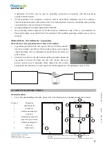
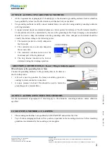
Do not install or handle the modules when they are wet or during periods of high wind.
Do not use or install broken modules.
If the front glass is broken, or the back sheet is torn, contact with any module surface or the frame can cause
electric shock.
Keep the junction box cover closed at all times.
Do not attempt to repair any part of the module. There’re no serviceable parts within the PV module.
Do not disassemble a module or remove any module part.
Do not artificially concentrate sunlight on a module.
Do not connect or disconnect modules when current from the modules or an external source is present.
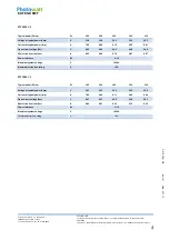
3.0 MECHANICAL / ELECTRICAL SPECIFICATIONS
The module electrical ratings are measured under Standard Test Conditions (STC) of 1 kW/m
2
irradiance with an
AM1.5 spectrum, and cell temperature of 25°C. The detailed electrical and mechanical characteristics of EDF
ENR PWT. crystalline silicon PV modules can be found in table A-2 of this manual (see Annex). Main electrical
characteristics at STC also appear on each module label. The maximum system voltage for all modules series is
either 600V or 1000V. Please refer to the datasheet or the product nameplate for the maximum system voltage.
Under certain conditions, a module may produce more current or voltage than its Standard Test Conditions (STC)
rated power. Accordingly, a module's open-circuit voltage and short-circuit current at STC should be multiplied
by 1.25 when determining
component voltage ratings, conductor ampacities, overcurrent device ratings, and size
of controls connected to the PV output. An additional 1.25 multiplier for a short-circuit current (for a total of
1.56), for sizing conductors and fuses may be applicable, as described in section 690-8 of U.S. NEC.
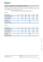
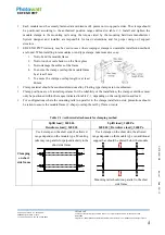
3.1 DIODES
Diodes inside the junction box should meet the requirements below:
Table 3-1: By-pass diode specifications
Module series
Number of
bypass diodes
Number of cells by
diodes
Diode ratings
Diode
type
Voltage Current
PW2350 UL
3
12
≥
40V
≥
15 A
Schottky
diodes
PW2500 UL
3
12
PW2850 UL
3
24
PW3000 UL
3
24
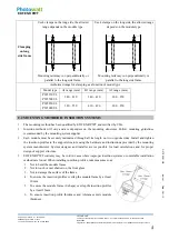
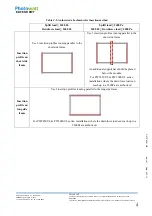
Diode configurations as below:


