background image

51

PAA6 

English


4. 

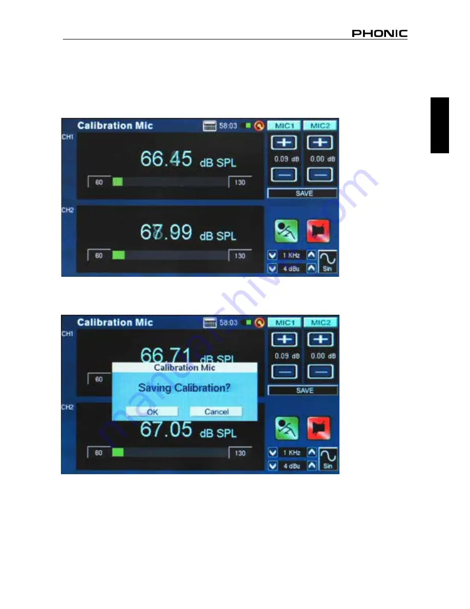
Adjust the level measured from the SPL calibrator by pressing “+” and “–“ buttons until the level is 
equal to that of the sound level calibrator (typically 94 dB). Pressing the “+” button each time will 

increase the value by 0.1dB; pressing the “–“ button each time will decrease the value by 0.1 dB 
(figure 70).

5. 

Press the SAVE button to complete the calibration (the PAA6 will restart in this case) or the BACK 

button to exit without saving. (figure 71 shows the saving calibration confirmation screen)

figure 70

figure 71

Summary of Contents for PAA6

Page 1: ...PAA6 User s Manual Manual del Usuario...

Page 2: ...English Espa ol 2 Channel Audio Analyzer with Color Touch LCD Analizador de Audio de 2 Canales con LCD T ctil de Color ENGLISH I ESPA OL II APPEDNIX III V2 3 10 21 2013 PAA6...

Page 3: ...Fourier Transform FFT 23 Reverb Time RT60 25 THD N 29 Meter 31 Phase 34 Scope 36 Polarity 38 LEQ 40 MEMORY 42 SETTINGS 44 SIGNAL GENERATOR 47 SYSTEM SETUP 49 MICROPHONE CALIBRATION 50 SPECIFICATIONS 5...

Page 4: ...ing lighting storms or when unused for long periods of time 14 Refer all servicing to service personnel Servicing is required when the apparatus has been damaged in any way such as power supply cord o...

Page 5: ...to obtain accurate measurements and guarantee the best pos sible quality of sound that any professional would expect We at Phonic took the utmost of care in ensuring the PAA6 is an extremely accurate...

Page 6: ...h this button to activate RUN the currently selected function Push it again to deactivate STOP the function When a function is run ning the accompanying LED will light up 4 Signal Generator Button and...

Page 7: ...download saved readings to and from the PAA6 or any SD card inserted into the PAA6 s SD card slot Real time operation will also possible through a future online update so please check www phonic com...

Page 8: ...bar gives users an indication of the current battery levels When the indicator turns red it s advised that you con nect the DC power adapter to the unit A full green bar means the battery is fully ch...

Page 9: ...ently selected operation 10 FILE Icon Users can select this icon to load save or delete any of their readings Read ings can be saved to either the PAA6 itself or an external SD card and are saved as t...

Page 10: ...ected filter mode will be indicated here whether it s flat 1 3 octave or 1 octave 15 Signal Generator Level As with the above option users can adjust the signal generator s output signal level without...

Page 11: ...t reads Memory followed by a slot number 0 1 2 3 and so forth Push the up and down arrows figure 1 to change the memory slot number click the memory slot name to save Green text indicates that data ha...

Page 12: ...6 or Line1 Line2 icons to deactivate the corresponding channels allowing users to read only the results of the other channel If you feel the PAA6 has stopped working be sure you haven t simply deactiv...

Page 13: ...9 PAA6 English figure 5 figure 6 figure 7...

Page 14: ...10 seconds to turn it off If you need to make quick calculations the PAA6 s calculator can be brought up without quitting your current function figure 8 Particularly usefully in RTA mode if you re fin...

Page 15: ...ading measurements off the screen without touching it be sure to turn the backlight s sleep mode off otherwise the screen will go dark after a few minutes see figure 11 This is done through the System...

Page 16: ...ttons on the left of the PAA6 may be quicker than pushing the onscreen icons The PAA6 cannot be charged through the USB connector To charge the unit the provided DC power adapter needs to be connected...

Page 17: ...arious audio analysis functions that the PAA6 provides There are nine in total see figure 13 all of which are easily accessibly through the main menu If at any point you wish to access a new feature s...

Page 18: ...dB range is displayed at any one time and users can scroll up the page slightly if clipping occurs or scroll down if the results aren t visible Frequencies from 20 Hz to 20 kHz can be monitored indivi...

Page 19: ...15 PAA6 English Procedure for taking acoustic measurements 1 Enter the SET menu on the RTA screen and change the input source to Mic see figure 18 figure 17 figure 18...

Page 20: ...RTA 2 3 octave resolution for a total of 15 bands 1 3 octave resolution for a total of 31 bands or 1 6 octave resolution for a total of 61 bands 3 Also in the settings menu set the appropriate weight...

Page 21: ...17 PAA6 English 4 Adjust response time peak hold frequency detect or other relevant properties as needed below figure 21 figure 22 figure 23...

Page 22: ...hannel properties listed The top value will be the dB SPL results for the currently selected band below which you will find the center frequency of the currently selected band if the all frequency bar...

Page 23: ...down the screen to see the lower levels 10 You can save your readings by entering the FILE menu and saving to either the PAA6 or inserted memory card figure 26 Procedure for measuring an electrical s...

Page 24: ...nse time weighting octave peak hold frequency detect and Subtract Sum figure 29 properties 3 Send a signal through the PAA6 s female XLR jacks The wiring should be as follows Pin 2 Hot Pin 3 Cold Pin...

Page 25: ...d memory card as shown in figure 26 EQ Setting figure 31 Also included within the RTA is an EQ setting function Pushing the onscreen icon will allow you monitor the suggested equalizer band settings u...

Page 26: ...esults from channel 1 to those of channel 2 together or subtract either channel from the other to compare the difference in level This option is set up in the SET menu and is activated by pushing the...

Page 27: ...ropriate position This usually means somewhere pointing at the ceiling preferably directed away from all loudspeakers in your setup 2 Set the frequency range that best suits your needs The following a...

Page 28: ...ed over two pages meaning you can actually scroll to the left or right to view more results This is done by the pushing the frequency values in the bottom left and right hand corners of the display wi...

Page 29: ...which can be selected from 10 preset values Working out the average of many different RT60 readings from around a room allows users to get an idea as to how much absorption or reflection of audio the...

Page 30: ...dio system this can be done using the PAA6 s signal generator or an audio test CD Make sure that if you re sending the pink noise from the PAA6 that the trigger is set to internal If you re getting th...

Page 31: ...Moving the red and yellow vertical lines on the RT60 graph will allow you to refine your RT60 results Position one of these lines at the beginning of the decay slope and the other at the bottom to get...

Page 32: ...requency only figure 42 Trigger Mode figure 43 two trigger modes are provided in the setup menu Internal Use this mode when the PAA6 generator output is used to provide the pink noise or other tone fo...

Page 33: ...such a piece of equipment however In the case of THD N not only are the signals directly related to the audio signal tested but so are other bits and pieces of audio that are not directly related to...

Page 34: ...en 100 Hz and 10 kHz at least and the average of these results calculated 5 Select the RUN STOP icon or push the RUN STOP button to the left of the PAA6 6 To the right of the display you should find t...

Page 35: ...red input source The dBu dBV and Volt measurements can be taken through the line inputs and give visual representations of their respective levels Taking SPL measurements 1 Enter the SET menu within t...

Page 36: ...he Maximum SPL level by simply selecting the word Max on screen Taking measurements through the line inputs 1 Enter the SET menu within the Meter function and set your input source to Line in You can...

Page 37: ...The measurement range will depend on the unit selected in the settings Each unit type has three different ranges that can be selected When operating under dBu the range can be adjusted between 85 to 2...

Page 38: ...the phase meter 2 Adjust the measurement range for the phase meter The measurement range will depend on the unit selected in the settings When operating under dBu the range can be adjusted between 85...

Page 39: ...line that lays perfectly horizontal along the X axis shows two signals that are perfectly out of phase and that will cancel each other out when played in mono A vertical line a line that runs along th...

Page 40: ...can be used for a multitude of measurements both through the mic and line inputs 2 Set the range of measurements taken The range can depend on the unit selected in point 1 In dB SPL users can select 3...

Page 41: ...er Users can select channel 1 channel 2 or both as the Scope s trigger see figure 55 Setting the trigger on one of or both of the channels allows users to better read the results of repeating waveform...

Page 42: ...erator Procedure for checking the polarity of speakers 1 Go to the Polarity function 2 Go to the SET menu figure 56 and select MIC as your input source Exit the setting menu 3 Connect the signal gener...

Page 43: ...ake sure the sound pressure level of the polarity signal from the system is higher than the noise from the surrounding environment The PAA6 will not be able to detect the phase of the speaker accurate...

Page 44: ...hing SET on the LEQ function page figure 58 Users can adjust the weighting and duration here As previously stated A weighting is more preferable in dB SPL situ ations as the results will mimic that of...

Page 45: ...he LEQ Results will be updated frequently on screen figure 59 6 Pushing the RUN STOP button again will stop the LEQ and freeze the current results on screen Once the LEQ has been stopped however it ca...

Page 46: ...top left of the page figure 60 3 Choose the appropriate location for your save file from either the PAA6 or an SD card figure 60 4 Select the small keyboard icon to the right of the window figure 60...

Page 47: ...3 Select the location from which you wish to load your previously recorded data 4 Select the file from the list that appears on screen figure 62 5 Push OK to continue 6 Once you load any file you can...

Page 48: ...may include dB SPL when the microphone is selected as the input source dBu dBV and Volt when line is selected as the input source 3 Response Time This feature allows users to select the speed at whic...

Page 49: ...easurements taken to compensate for the increased and decreased sensitivity The weighting determines the curve that the PAA6 will use to interpret the input signals from the chosen input source Flat A...

Page 50: ...Filter Mode Frequency figure 65 On the RT60 function this setting allows users to select one of the preset frequencies to calculate their RT60 measurements Even after performing an RT60 calcula tion...

Page 51: ...tave intervals selectable by the user Alternatively users can choose Select and adjust the sweep range manual Once users choose Select the Sweep start and Sweep stop fields will become active and user...

Page 52: ...heck the Polarity section of the menu for more information Pink Noise The pink noise signal is typically used for adjustment of environment acoustics The most common use would be in the setting of equ...

Page 53: ...of the screen can help preserve battery power or increasing it can enhance visibility in bright areas The display section also features a backlight time option that allows users to adjust the time the...

Page 54: ...quality sound level calibrator with 1 2 diameter adapter that sends out a 1 kHz tone A B K TYPE 4231 sound level calibrator is suggested Procedure 1 Enter the System Calibration Mic menu figure 69 2...

Page 55: ...ically 94 dB Pressing the button each time will increase the value by 0 1dB pressing the button each time will decrease the value by 0 1 dB figure 70 5 Press the SAVE button to complete the calibratio...

Page 56: ...5dB steps on Y Axis Unit dB SPL dBu dBV Volt Octave 1 1 1 3 2 3 1 6 Weighted A B C Flat FFT Frequency Range 13 selectable bandwidths Subtract Sum CH1 CH2 CH1 CH2 CH2 CH1 Unit dB SPL dBu dBV Volt Octav...

Page 57: ...the date of purchase You will need it for any warranty service No returns or repairs will be accepted without a proper RMA number return merchandise authorization In order to keep this warranty in eff...

Page 58: ...de Reverberaci n RT60 25 Distorsi n Arm nica Total Ruido 29 Medidor 31 Fase 34 Scope 36 Polaridad 38 Nivel de Ruido Continuo Equivalente 40 MEMORIA 42 CONFIGURACIONES 44 GENRADOR DE SE AL 47 CONFIGURA...

Page 59: ...55 PAA6 Espa ol...

Page 60: ...ara obtener mediciones exactas y garantizar la mejor calidad del sonido que cualquier profesional esperar a En Phonic tomamos el m ximo cuidado para asegurar que el PAA6 sea medio extremada mente exac...

Page 61: ...Bot n Ejecutar Parar e Indicador Pulse este bot n para activar RUN la funci n seleccionada actualmente Pulselo nuevamente para desactivar STOP la funci n Cuando una funci n est ejecutando el LED acom...

Page 62: ...y desde el PAA6 o cualquier tarjeta SD in sertada en la ranura para tarjeta SD de PAA6 La operaci n en tiempo real tambi n es posible a trav s de una actualizaci n futura en l nea por favor chequee ww...

Page 63: ...tamente haciendo click sobre la hora en la parte superior de la pantalla para traer los ajustes de la hora Como la calcula dora sacar el men de la hora no afectar a la funci n actual 5 Indicador de Ba...

Page 64: ...los par metros apropiados de su operaci n actualmente seleccionada 10 Icono Archivo Los usuarios pueden selec cionar este icono para cargar guardar o borrar cualquiera de sus lecturas Las lecturas pue...

Page 65: ...tualmente ser indicado aqu sea plano 1 3 octava o 1 octava 15 Nivel de Generador de Se al Como con la opci n antedicha los usuarios pueden ajustar el nivel de se al de salida del generador de se al si...

Page 66: ...por un n mero de ranura 0 1 2 3 y as sucesivamente Pulse las flechas hacia arriba y hacia abajo figura 1 para cambiar el n mero de ranura de la memoria haga click en el nombre de la ranura de memoria...

Page 67: ...guras 4 6 para desactivar los canales correspondientes permitiendo a los usuarios lear solamente los resultados del otro canal Si usted siente que el PAA6 ha dejado de funcionar asegurese que no ha de...

Page 68: ...PAA6 9 Espa ol figura 5 figura 6 figura 7...

Page 69: ...cendido por 10 segundos para apagarlo Si usted necesita hacer c lculos r pidos la calculadora de PAA6 puede ser tra da sin salir de su funci n actual figura 8 Particularmente til en modo RTA si usted...

Page 70: ...es de lectura de la pantalla sin tocarla aseg rese de setear el modo sleep de la luz de fondo en off de lo contrario la pantalla se volver oscura despu s de unos minutos figura 11 Esto se hace a trav...

Page 71: ...hibici n m xima de SPL pulse simplemente la palabra Max en la pantalla figura 12 Pulsando los botones de Ejecutar Parar y Generador de Se al S G en la izquierda del PAA 6 puede ser m s r pido que puls...

Page 72: ...de an lisis de audio que el PAA6 propor ciona Hay nueve en total figura 13 que son f cilmente accesibles a trav s del men principal Si en cualquier momento usted desea tener acceso a una nueva caracte...

Page 73: ...ento y los usuarios pueden desplazar la p gina hacia arriba levemente si produce recortes o hacia abajo si los resultados no son visibles Las frecuencias de 20 Hz a 20 kHz pueden ser monitoreadas indi...

Page 74: ...PAA6 15 Espa ol Procedimiento para tomar mediciones ac sticas 1 Ingrese al men SET en la pantalla de RTA y cambie la fuente de entrada a Mic figura 18 figura 17 figura 18...

Page 75: ...n RTA resoluci n 2 3 octava para un total de 15 bandas resoluci n 1 3 octava para un total de 31 bandas o resoluci n 1 6 octava para un total de 61 bandas 3 Tambi n en el men de los ajustes setee la p...

Page 76: ...PAA6 17 Espa ol 4 Ajuste el tiempo de repuesta peak hold detecci n de frecuencia u otras propiedades relevantes como sea necesario vea a continuaci n figura 21 figura 22 figura 23...

Page 77: ...adas El valor superior ser los resultados de dB SPL para la banda actualmente seleccionada debajo del cual usted encontrar la frecuencia de centro de la banda actualmente seleccionada si se elige la b...

Page 78: ...jo por la pantalla para ver los niveles inferiores 10 Usted puede almacenar sus lecturas ingresando al men FILE archivo y guardar al PAA6 o a la tarjeta de memoria insertada figura 26 Procedimiento pa...

Page 79: ...esta ponderaci n octava peak hold detec ci n de frecuencia y las propiedades de Resta Suma figura 29 3 Env e una se al a trav s de los jacks hembra XLR de PAA6 El cableado debe ser como sigue Pin 2 Ho...

Page 80: ...rado en figura 26 Seteo de EQ figura 31 Tambi n se incluye dentro de RTA una funci n de ajuste de EQ Pulsando el icono en pantalla le permitir monitorear los ajustes sugeridos de la banda del ecualiza...

Page 81: ...tar sumar los resultados de canal 1 a los del canal 2 juntos o restar cualquier canal del otro para comparar la diferencia en nivel Esta opci n se setea en el men SET y es activada pulsando el icono e...

Page 82: ...mplio como 0 2 Hz a 20 kHz puede ser monitoreado usando la funci n de FFT Tomando las mediciones FFT 1 Coloque el micr fono de PAA6 en una posici n apropiada Esto significa generalmente alguna parte a...

Page 83: ...l bot n de RUN STOP otra vez en cualquier momento para hacer una pausa la FFT 7 Los resultados de FFT se exhiben sobre dos p ginas significa que usted puede desplazar real mente a la izquierda o derec...

Page 84: ...cia puede ser seleccionada de los 10 valores preseteados La elaboraci n del promedio de muchas diferentes lecturas RT60 alrededor de un cuarto permite que los usuarios consigan una idea en cu nta abso...

Page 85: ...e hacer usando el generador de se al de PAA6 o un CD de prueba de audio Cerci rese de que si usted est enviando el ruido rosa de PAA6 el trigger est seteado a interno Si usted est obteniendo el ruido...

Page 86: ...s verticales rojas y amarillas en el gr fico RT60 permitir que usted refine sus resultados RT60 Coloque una de estas l neas al principio de la pendiente del decaimiento y la otra en la parte inferior...

Page 87: ...gura 42 Modo Trigger figura 43 dos modos de trigger son proporcionados en el men de la configuraci n Interno Utilice este modo cuando la salida del generador PAA6 se utiliza para proporcionar el ruido...

Page 88: ...de THD N no s lo est n las se ales relacionadas directamente con la se al de audio testeada sino tambi n otros bits y piezas de audio que no se relacionan directamente con la se al El ruido ronquido z...

Page 89: ...ente entre 100 Hz y 10 kHz por lo menos y el promedio de estos resultados calculados 5 Seleccione el icono de RUN STOP o pulse el bot n de RUN STOP a la izquierda del PAA6 6 A la derecha de display us...

Page 90: ...eada Las mediciones dBu dBV y Voltio pueden ser tomadas a trav s de las entradas de l nea y brindan representaciones visuales de sus niveles respectivos Mediciones de SPL 1 Ingrese al men SET dentro d...

Page 91: ...o de SPL simplemente seleccionando la palabra Max en la pantalla Tomando mediciones a trav s de las entradas de l nea 1 Ingrese al men SET dentro de la funci n Medidor y setee su fuente de entrada a L...

Page 92: ...mismo El rango de la medici n de pender de la unidad seleccionada en los ajustes Cada tipo de unidad tiene tres diferentes rangos que pueden ser seleccionados Cuando se opera bajo dBu el rango puede a...

Page 93: ...cione OK para regresar a medidor de fase 2 Ajuste el rango de la medici n para el metro de fase El rango de la medici n depender de la unidad seleccionada en los ajustes Cuando se opera bajo dBu el ra...

Page 94: ...se Una l nea que pone perfectamente horizontal a lo largo del eje X muestra dos se ales que est n perfectamente fuera de fase y que se anulan mutuamente cuando est n en mono Una l nea vertical una l n...

Page 95: ...ger El scope puede ser utilizado para una multiplicidad de mediciones a trav s entradas de micr fono y de l nea 2 Setee el rango de las mediciones tomadas El rango puede depender de la unidad seleccio...

Page 96: ...l 1 canal 2 o ambos como el trigger de Scope figura 55 La determinaci n del trigger en uno o ambos de los canales permite a los usuarios leer mejor los resultados de la repetici n de formas de mover e...

Page 97: ...or de se al a las entradas de sistema de sonido Idealmente con los altavoces activos usted conectar el generador de se al en sus altavoces para evitar la complicaci n de encontrar los cables mal cable...

Page 98: ...Cerci rese de que el nivel de presi n de sonido de la se al de polaridad desde sistema sea m s alto que el ruido del entorno El PAA6 no podr detectar la fase del altavoz correctamente si la se al de p...

Page 99: ...Q pulsando SET en la p gina de funci n LEQ figura 58 Los usuarios pueden ajustar la ponderaci n y duraci n aqu Como lo indicado previamente la ponderaci n A es m s preferible en situaciones dB SPL pue...

Page 100: ...ultados ser n actualizados frecuentemente en la pantalla figura 59 6 Pulsando el bot n de RUN STOP nuevamente parar el LEQ y congelar los resultados actuales en la pantalla Sin embargo una vez que se...

Page 101: ...60 3 Elija la localizaci n apropiada para almacenar su archivo de PAA6 o de una tarjeta SD figura 60 4 Seleccione el peque o icono de teclado a la derecha de la ventana figura 60 5 Ingrese un t tulo...

Page 102: ...ocalizaci n que usted desea cargar sus datos previamente guardados 4 Seleccione el archivo de la lista que aparece en la pantalla figura 62 5 Pulse OK para continuar 6 Una vez que usted carga cualquie...

Page 103: ...ndo el micr fono es seleccionado como la fuente de entrada dBu dBV y Voltio cuando la l nea es seleccionado como la fuente de entrada 3 Response Time Tiempo de Respuesta Esta caracter stica permite qu...

Page 104: ...iciones para compensar la sensibilidad incrementada o descrementada La ponderaci n determina la curva que el PAA6 usar para interpretar las se ales de entrada desde fuente de entrada elegida Est n dis...

Page 105: ...o de Filtro Frecuencia figura 65 En la funci n RT60 este ajuste permite que los usuarios seleccionen una de las frecuencias preseteadas para calcular sus medicio nes RT60 Incluso despu s de realizar u...

Page 106: ...eleccionables de 1 6 1 3 2 3 y 1 oc tava por el usuario Alternativamente los usuarios pueden elegir Select y ajustar el rango de barrido manualmente Una vez que los usuarios eligen Select los campos d...

Page 107: ...informaci n Pink Noise Ruido Rosa La se al de ruido rosa es t picamente utilizada para ajustar los ac sticos de entorno El uso m s com n ser a en la configuraci n de ecualizadores Un ruido rosa abarc...

Page 108: ...el brillo de la pantalla puede ayudar a preservar la energ a de bater a o aumentandolo puede realzar visibilidad en reas brillantes La secci n de display tambi n ofrece una opci n del tiempo de contr...

Page 109: ...ga un calibrador del nivel de sonido de calidad con adaptador de di metro de 1 2 que env a un tono de 1 kHz Se sugiere calibrador de nivel de sonido A B K TYPE 4231 Procedimiento 1 Ingrese al men Syst...

Page 110: ...l calibrador del nivel de sonido t picamente 94 dB Presionando el bot n aumentar cada vez el valor en 0 1dB presionando el bot n disminuir cada vez el valor por 0 1 dB figura 70 5 Presione el bot n SA...

Page 111: ...rosa ruido blanco RTA Frecuencia 20 Hz 20 KHz todas las frecuencias Seteo de EQ EQ Corte o Aumento Resta Suma CH1 CH2 CH1 CH2 CH2 CH1 Rango Din mico 30 130 dB 60dB rango de display ej 70 130 60 120 50...

Page 112: ...o en fase Alcance del Oscilador Trigger CH1 CH2 CH1 CH2 Modo Auto Normal Polaridad Chequeador de Polaridad Negativo Positivo LEQ Ponderaci n A B C Flat KHz Frecuencia Selectable Bater as DC3 7V 2200m...

Page 113: ...fecha de compra Va a necesitar este comprobante para cualquier servicio de garant a No se aceptar n reparaciones o devoluciones sin un n mero RMA apropiado return merchandise autorization En orden de...

Page 114: ...PAA6 1 Appendix DIMENSIONS DIMENSION Measurements are shown in mm inches Todas las medidas est n mostradas en mm pulgadas 174 5mm 6 89 7 1 4 m m 5 5 0 1 40mm 1 57...

Page 115: ...2 PAA6 Appendix NOTES...

Page 116: ......

Reviews: