


Firefly 302 USB
20
Firefly 302 USB Control Panel
As many of the Firefly’s features are ad
-
justable through the Audio MIDI Setup
section, the Firefly302USB Control Panel
serves a few very specific surfaces. As
seen in the image below, the main page
of the software allows users to view a few
important details on the product, including
the driver version, serial number, etcet-
era.
Users can also select one of the two in-
ternal mixers that the Firefly’s software
offers.
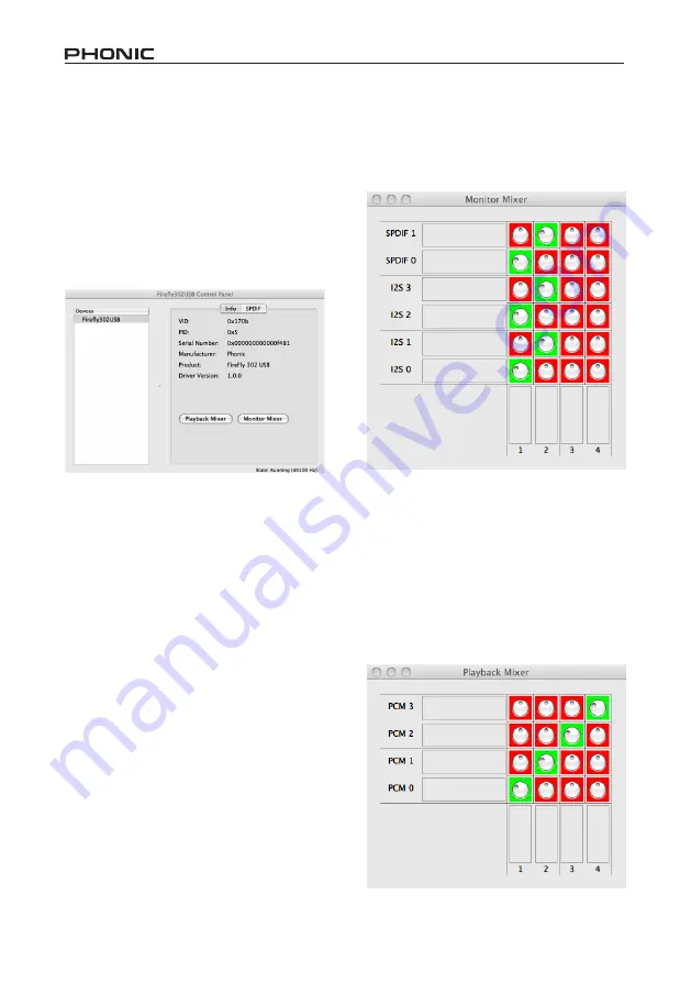
Monitor Mixer
The Monitor Mixer, in essence, allows you
to adjust your Firefly’s input signals before
sending them off to your DAW software.
All of the inputs are listed; the SPDIF 1
and 0 inputs that are listed in the software
are representative of the S/PDIF left and
right input signals, I2S 3 and 2 are both
the microphone input, and the I2S 1 and 0
channels are analog inputs 1 and 2 on the
Firefly 302 USB.
You can opt to adjust your device’s input
signals in this mixer, or you can just opt to
leave it alone all together and rely on your
DAW software’s level controls.
In case you’re wondering why there’s only
one microphone input, but two micro-
phone channels on the Firefly - this func
-
tion allows you to make a stereo mix of
your microphone signal!
Playback Mixer
The control panel software also offers
a Playback Mixer. This is the ‘software
mixer’, allowing users to adjust the signal
they send out to the Firefly 302 USB’s out
-
puts. All of the output signals from your
DAW software can be adjusted individu-
ally before being sent out their respective
outputs on the Firefly.
Summary of Contents for FIREFLY 302 USB
Page 1: ...Firefly 302 USB Portable USB Audio Interface...
Page 14: ...Firefly 302 USB 14 Click Close once the installation has completed...
Page 27: ...6103 Johns Road 7...
Page 28: ......


