background image

QUINT4-PS/12-24DC/5-15DC/2.5/PT

110260_en_00

PHOENIX CONTACT

17/30

7.4

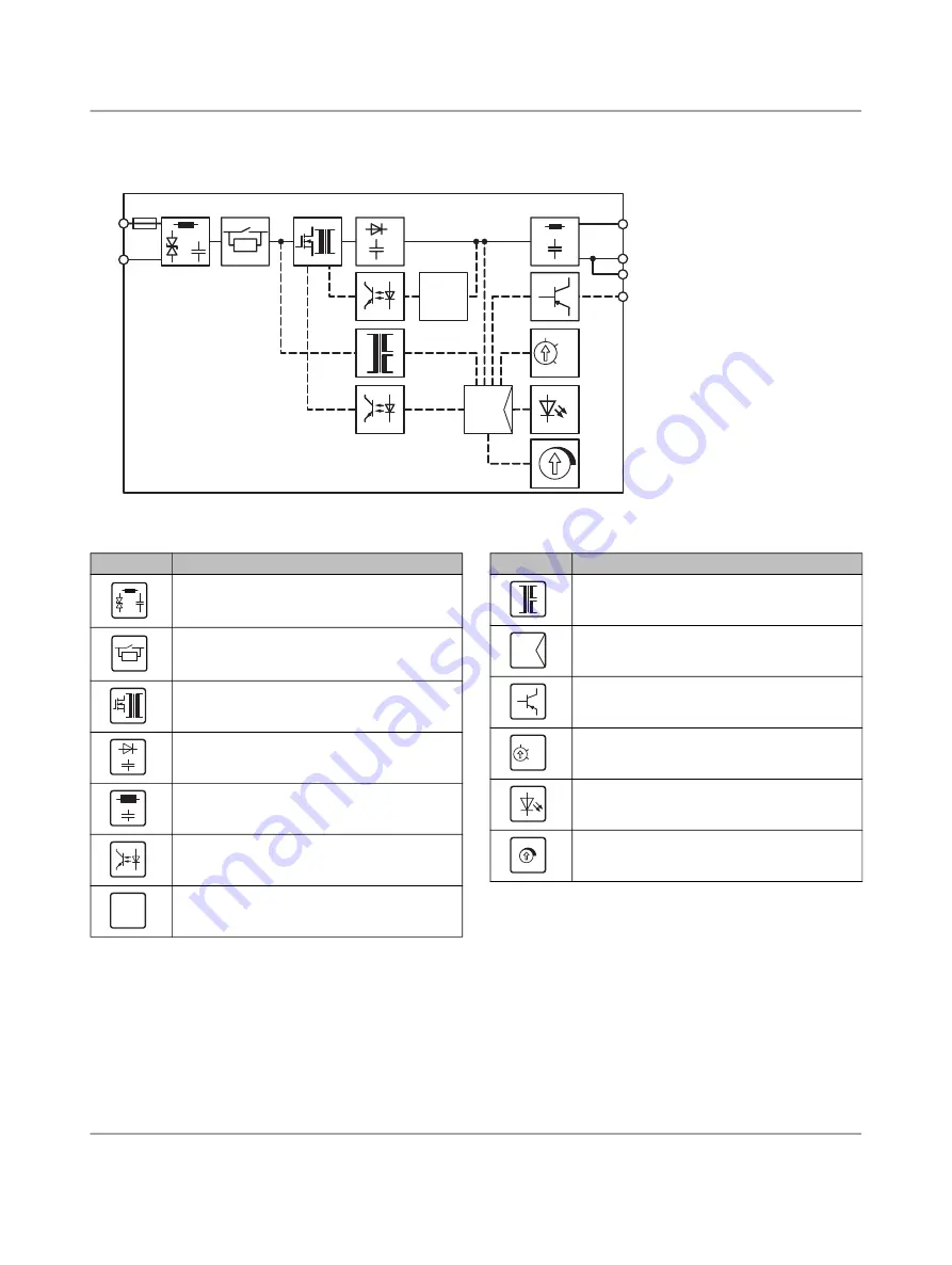
Block diagram

Figure 6

Block diagram

Key

OVP

SIG

Ď

C

3.1

SIG

2.2
2.3

-

2.1

+

1.1

+

1.2

-

-

Symbol

Designation

Surge protection (diode) with filter

Inrush current limitation

Switching transistor and main transmitter 

(electrically isolating)

Secondary rectification and smoothing

Filter

Optocoupler (electrically isolating)

Additional regulatory protection against 

surge voltage

OVP

Symbol

Designation

Auxiliary converter (electrically isolating)

Microcontroller

PNP transistor switch output

Rotary selector switch

Signal/display LEDs

Potentiometer output voltage

C

SIG

Summary of Contents for QUINT4-PS/12-24DC/5-15DC/2.5/ PT

Page 1: ...ow power dissipation Technical data short form Input voltage range 12 V DC 24 V DC 25 33 Mains buffering typ 20 ms 24 V DC Nominal output voltage UN 12 V DC Setting range of the output voltage USet 5 V DC 15 V DC Nominal output current IN Static Boost IStat Boost Dynamic Boost IDyn Boost 2 5 A 3 125 A 40 C 5 A 60 C 4 9 s Output power PN Output power PStat Boost Output power PDyn Boost 30 W 37 5 W ...

Page 2: ... 3 Ordering data 3 4 Technical data 4 5 Safety and installation notes 13 6 High voltage test HIPOT 14 7 Structure of the power supply 15 8 Mounting removing the power supply 18 9 Device connection terminal blocks 20 10 Output characteristic curves 20 11 Boost currents 21 12 Signaling 23 13 Operating modes 25 14 Derating 27 ...

Page 3: ...s Type Order No Pcs Pkt Screwdriver flat bladed size 0 4 x 2 0 x 60 mm 2 component grip with non slip grip SF SL 0 4X2 0 60 1212546 10 Type 3 surge protection consisting of protective plug and base element with integrated status indicator and remote signaling for single phase power supply networks Nominal voltage 24 V AC DC PLT SEC T3 24 FM UT 2907916 5 The range of accessories is being continuous...

Page 4: ... 5 A Inrush current integral I2t typ 0 05 A2s Input fuse fast blow internal 15 A During the first few microseconds the current flow into the filter capacitors is excluded The SCCR value short circuit current rating of the power supply unit corresponds to the SCCR value of the backup fuse see input protection table The external backup fuse must be approved for the DC supply voltage used and the vol...

Page 5: ...0 2 5 3 0 3 5 4 0 0 0 0 5 1 0 1 5 2 0 2 5 3 0 3 5 4 0 Ĵ UIn 12 V DC UOut 12 V DC ĵ UIn 24 V DC UOut 12 V DC Input connection data Connection method Push in connection Conductor cross section rigid 0 5 mm 2 5 mm Conductor cross section flexible 0 5 mm 2 5 mm Conductor cross section flexible with ferrule with plastic sleeve 0 5 mm 2 5 mm Conductor cross section flexible with ferrule without plastic ...

Page 6: ...in series yes Feedback voltage resistance 25 V DC Protection against overvoltage at the output OVP 18 V DC Rise time typical 1 s UOUT 10 90 Output connection data Connection method Push in connection Conductor cross section rigid 0 2 mm 2 5 mm Conductor cross section flexible 0 5 mm 2 5 mm Conductor cross section flexible with ferrule with plastic sleeve 0 5 mm 2 5 mm Conductor cross section flexi...

Page 7: ...2 5 A 226000 h 40 C 2 5 A 452000 h 30 C The expected service life is based on the capacitors used If the capacitor specification is observed the specified data will be ensured until the end of the stated service life For runtimes beyond this time error free operation may be reduced The specified service life of more than 15 years is simply a comparative value Switching frequency Min Max Auxiliary ...

Page 8: ...eration refers to IEC 61010 surrounding air temperature Ambient temperature start up type tested 40 C Ambient temperature storage transport 40 C 85 C Max permissible relative humidity operation 95 at 25 C non condensing Installation height 5000 m 2000 m observe derating Vibration operation 15 Hz 2 5 mm amplitude 15 Hz 100 Hz 2 3 g 90 Min in accordance with IEC 60068 2 6 Shock 18 ms 30g in each spa...

Page 9: ... EMC requirements power plant EN 61850 3 EN 61000 6 5 Approvals UL UL Listed UL 61010 1 CAN CSA C22 2 No 61010 1 12 UL Listed UL 61010 2 201 CAN CSA C22 2 No 61010 2 201 18 UL 121201 CSA C22 2 No 213 17 Class I Division 2 Groups A B C D T4 Hazardous Location CB Scheme IEC 61010 1 IEC 61010 2 201 Shipbuilding DNV GL Current approvals permissions for the product can be found in the download area und...

Page 10: ...00 6 1 residential EN 61000 6 2 industrial and EN 61000 6 5 power station equipment zone IEC EN 61850 3 energy supply CE basic standard Minimum normative requirements of EN 61000 6 2 CE immunity for industrial environments Higher requirements in practice covered Electrostatic discharge EN 61000 4 2 Housing contact discharge 4 kV Test Level 2 8 kV Test Level 4 Housing air discharge 8 kV Test Level ...

Page 11: ...on A Criterion A Power frequency magnetic field EN 61000 4 8 50 Hz 60 Hz 30 A m 16 67 Hz 50 Hz 60 Hz 100 A m 60 s not required 50 Hz 60 Hz 1 kA m 3 s not required 0 Hz 300 A m DC 60 s Comments Criterion A Criterion A Immunity according to EN 61000 6 1 residential EN 61000 6 2 industrial and EN 61000 6 5 power station equipment zone IEC EN 61850 3 energy supply CE basic standard Minimum normative r...

Page 12: ...cal 1 MHz 1 kV Test Level 2 asymmetrical Signals 1 MHz 0 5 kV Test Level 2 symmetrical 1 MHz 0 5 kV Test Level 2 symmetrical 1 MHz 1 kV Test Level 2 asymmetrical 1 MHz 1 kV Test Level 2 asymmetrical Comments Criterion B Criterion A Voltage dips EN 61000 4 29 Input voltage 24 V DC Voltage dip 70 100 ms Test Level 2 70 100 ms Test Level 2 Comments Criterion C Criterion A Voltage dip 40 100 ms Test L...

Page 13: ... are the correct size and have sufficient fuse protection For the connection parameters for wiring the power supply such as the required stripping length with and without ferrule refer to the technical data section Use copper cables for operating temperatures of 75 C ambient temperature 55 C 90 C ambient temperature 75 C Protect the device against foreign bodies penetrating it e g paper clips or m...

Page 14: ... higher Routine manufacturing tests are inspected regularly by a certification authority 6 3 High voltage dielectric test performed by the customer Apart from routine and type tests to guarantee electrical safety the end user does not have to perform another high voltage test on the power supply as an individual component According to EN 60204 1 Safety of machinery Electrical equipment of machines...

Page 15: ...nal block output voltage Output DC 3 Accommodation for cable binders 4 Integrated snap on foot for carrier rail mounting 5 QR code web link 6 Connection terminal block input voltage Input 7 Signaling DC OK LED 8 Rotary selector status ofthe output voltage DC OK or output power POut PThr 9 Signaling POut PThr LED yellow output power POut output power threshold PThr 10 Potentiometer output voltage I...

Page 16: ...m keep out areas in mm Nominal output capacity Spacing mm a b c 50 0 30 30 50 5 30 30 If adjacent components are active and the nominal output power 50 there must be lateral spacing of 15 mm 99 b c 22 5 a a QUINT POWER Ord No xxxxxxx Output DC SIG 3 1 2 1 2 2 Input DC 1 1 1 2 Boost 100 75 50 DC OK Signal SIG UOut POut PThr ...

Page 17: ...sh current limitation Switching transistor and main transmitter electrically isolating Secondary rectification and smoothing Filter Optocoupler electrically isolating Additional regulatory protection against surge voltage OVP Symbol Designation Auxiliary converter electrically isolating Microcontroller PNP transistor switch output Rotary selector switch Signal display LEDs Potentiometer output vol...

Page 18: ... the integrated snap on foot audibly latches into place B 3 Check that the power supply is securely attached to the DIN rail Figure 7 Snapping the power supply onto the DIN rail 8 2 Removing the power supply unit Proceed as follows to remove the power supply 1 Take a suitable screwdriver and insert this into the lock hole on the integrated snap on foot A 2 Release the lock by lifting the screwdriv...

Page 19: ... connection wiring is attached safely and securely without damaging the connection wiring Figure 10 Secure connection wiring with cable binder Shorten the excess length of the cable ties Then check again that the connection wiring is properly secured Figure 11 Shorten protruding ends of the cable binder QUINT POWER QUINT POWER Ord No 290xxxx Ord No 290xxxx Output SIG 3 1 2 1 2 2 Boost 100 75 P P O...

Page 20: ...t circuit proof and no load proof In the event of an error the output voltage is limited 10 Output characteristic curves The U I output characteristic curve is optimized for the following applications When supplying loads with high switch on currents such as motors The dynamic boost of the power supply supplies up to 200 of the nominal power for 5 s This ensures that sufficient reserve energy is a...

Page 21: ...determine the required recovery time tPause at the maximum dynamic boost current IDyn Boost based on the following values IBase Load Duration of the boost current tDyn Boost Ambient temperature 40 C or 60 C 11 2 1 Recovery times at an ambient temperature of 40 C Figure 16 Required recovery times at 40 C 11 2 2 Recovery times at an ambient temperature of 60 C Figure 17 Required recovery times at 60...

Page 22: ...3 A the dynamic output current IDyn Boost of 5 A increases for 2 s tDyn Boost After a recovery time tPause of 6 s the dynamic boost is available once again Figure 18 Example recovery time for 40 C 1 7 5 3 4 7 8 2 8 6 8 11 14 2 1 4 2 6 8 10 4 1 8 8 15 12 23 16 31 20 39 5 1 2 3 4 5 5 5 5 5 0 6 1 3 1 9 2 5 0 0 t s Pause IBased Load IDyn Boost A A tDyn Boost s ...

Page 23: ...tch in position 50 75 or boost 100 In each of these switch positions the output power POut is monitored When the set threshold is exceeded the yellow LED lights up POut PThr and the signal output SIG switches to active low 12 3 Location and function of the signaling elements Figure 19 Position of signaling elements Key The following table shows the standard assignment for signaling for the U I cha...

Page 24: ...stalled in protected areas and has direct connections to other areas must satisfy the immunity criteria Use Phoenix Contact surge protection Order No 2905223 when you are using signal connection types p l f and h for the signal paths DIN EN 61000 6 5 Electromagnetic Compatibility EMC The interface area may include items such as equipment devices apparatus and systems connected to the outside world...

Page 25: ...ries operation 13 2 Parallel operation You can connect several power supplies in parallel in order to increase the power or to supply the loads redundantly Figure 24 Schematic diagram in parallel operation Observe the following points when carrying out parallel connection 1 Use power supplies of the same type and performance class 2 Setting the same output voltages 3 Using the same cable cross sec...

Page 26: ...hematic diagram redundant operation with diode Certain specifications apply in redundancy operation with regard to the configuration of the keepout areas In redundancy operation the power supplies are operated with maximum half the nominal power The keepout areas are therefore reduced The following conditions must be met for 1 1 and n 1 redundancy operation of the power supplies in conjunction wit...

Page 27: ...n output more than the nominal power for a sustained period Figure 27 Output power depending on the ambient temperature 14 2 Installation height The power supply can be operated at an installation height of up to 2000 m without any limitations Different data applies for installation locations above 2000 m due to the differing air pressure and the reduced convection cooling associated with this see...

Page 28: ... should be mounted horizontally for heat dissipation reasons input connection terminal blocks facing downward Please observe the derating for any mounting other than the normal mounting position Reduce the output power based on the prevailing ambient temperature The recommended output power for different mounting positions and ambient temperatures can be found in the characteristic curves below Ex...

Page 29: ...QUINT4 PS 12 24DC 5 15DC 2 5 PT 110260_en_00 PHOENIX CONTACT 29 30 14 3 3 Rotated mounting position 180 Z axis 14 3 4 Rotated mounting position 270 Z axis 0 1 2 13 2 0 1 2 13 2 ...

Page 30: ...m 14 3 5 Rotated mounting position 90 X axis 14 3 6 Rotated mounting position 270 X axis QUINTPOWER O rd N o x x x x x x x B o o s t 1 0 0 7 5 P o u t P T hr 5 0 D C O K U O u t 2 4 2 8 V S i g n a l S I G P Out Ą C 0 25 50 75 100 125 150 175 200 225 0 10 20 30 40 50 60 70 25 Ĵ ĵ Ķ PStat 125 PDyn 200 PN 100 Ĵ Ķ ĵ Z X Y ...

Reviews: