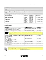
IB IL 24/230 DOR 4/W-PC (-PAC)
4
6530B
General Description
Figure 2
IB IL 24/230 DOR 4/W-PC
with an appropriate connector
Function Identification
Red with lightning bolt
Housing/Connector Color
Gray housing
Gray connector
Local LED Diagnostic and Status Indicators
Terminal Assignment for Each Connector
In the corresponding connector IB IL SCN-8-AC-REL,
the adjacent contacts
1.2/2.2, 1.3/2.3, and 1.4/2.4 are jumpered.
It is therefore possible to transmit the power to
supply several relays of IB IL 24/230 DOR 4/W-PC
terminals from one connector to the next via a
jumper.
1
2
1
2
3
4
1
2
3
4
1 . 1
1 . 2
1 . 3
1 . 4
2 . 1
2 . 2
2 . 3
2 . 4
6 5 3 0 A 0 0 3
1
2
D
D O R 4 / W
3
4
Des.
Color Meaning
D
Green Diagnostics
1, 2,
3, 4
Yellow Output status indicator
(relay has picked up)
Terminal
Points
Assignment
1.1, 2.1
Not used
(no contact present)
1.2, 2.2
Relay N/C contact
1.3, 2.3
Relay main contact
1.4, 2.4
Relay N/O contact
Please note that the current at one
terminal point must not exceed 8 A.


