Phoenix Contact FL FXT Quick Start Manual Download Page 12

FL SWITCH GHS

1-4

PHOENIX CONTACT

8042_en_00

1.4

Operability of the GHS 

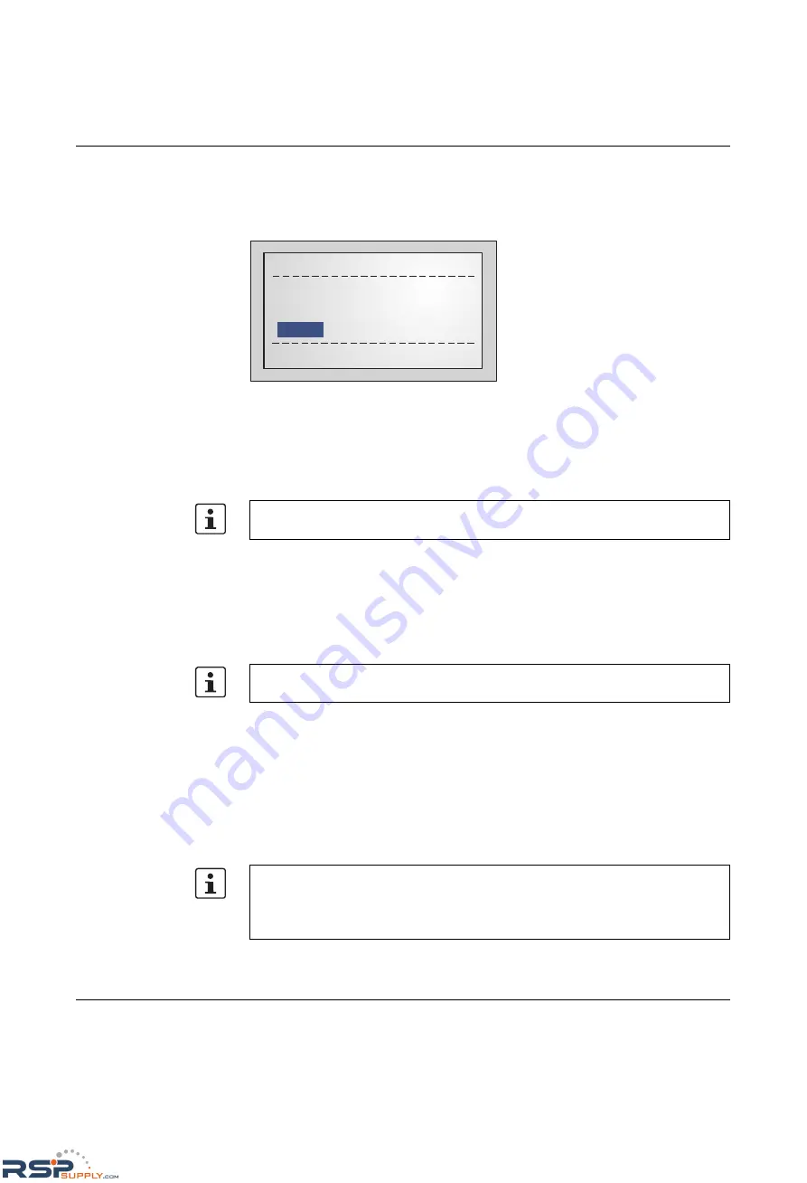
The device will boot automatically after you have connected the supply voltage. After a short 

time the display will show the following:

Figure 1-5

Display after termination of the boot phase in default upon delivery

When the device is in the default upon delivery, it will send BootP requests. The GHS tries 

to obtain IP addresses with these requests.

If your Switch displays something different, we recommend using the Smart Mode to reset 

it to the default state upon delivery.

Before you can access the web-based management of the GHS, the device must be 

assigned an IP address/IP parameters (see "Assigning IP parameters" on page 1-5) or the 

default IP address must be activated (see "Activating the default IP address" on page 1-4).

1.5

Activating the default IP address

After the boot phase, use the buttons/display to proceed as follows:

Press "Menu".

Select "IP Menu" and then press "Select".

Select "IP Settings" and then press "Select".

Select "Default IP" and then press "Set".

Now the Switch can be accessed with IP address: 

192.168.0.100

. You may have to adapt 

your PC (see "Making contact between the GHS and PC for initial configuration" on 

page 1-7). 

Please refer to the UM EN FL SWITCH GHS user manual for information on calling and 

using the Smart Mode.

Please refer to the UM EN FL SWITCH GHS user manual for information on how to use 

the display.

Please observe the following:

The selection of the default IP is not saved retentively. Save the desired configuration 

via the management interfaces.

Make sure that there is only one device with the IP 192.168.0.100 in your network.

No IP assigned (01)

MENU

MODE

SPD

FD

ACT

RSPSupply  -  1-888-532-2706 -  www.RSPSupply.com

http://www.RSPSupply.com/p-14161-Phoenix-Contact-2700271-FL-SWITCH-GHS-4G/12-Modular-Ethernet-Switch.aspx

Summary of Contents for FL FXT

Page 1: ...or FL SWITCH GHS 12G 8 FL SWITCH GHS 4G 12 Quick Start Guide Order No Gigabit Modular Switch RSPSupply 1 888 532 2706 www RSPSupply com http www RSPSupply com p 14161 Phoenix Contact 2700271 FL SWITCH...

Page 2: ...RSPSupply 1 888 532 2706 www RSPSupply com http www RSPSupply com p 14161 Phoenix Contact 2700271 FL SWITCH GHS 4G 12 Modular Ethernet Switch...

Page 3: ...to the web based management of the Gigabit Modular Switch UM QS EN FL SWITCH GHS 00 Designation Revision Order No FL SWITCH GHS 2989200 FL SWITCH GHS 4G 12 2700271 FL FXT 2989307 Quick start guide RSP...

Page 4: ...nformation concerning proper operation and ease of use This is the safety alert symbol It is used to alert you to potential personal injury hazards Obey all safety measures that follow this symbol to...

Page 5: ...guarantees as to the reliability accuracy or completeness of the information All information made available in the technical data is supplied without any accompanying guarantee whether expressly menti...

Page 6: ...our Terms and Conditions can be found on the Internet at www phoenixcontact com Make sure you always use the latest documentation It can be downloaded at www phoenixcontact net catalog Subsidiaries I...

Page 7: ...Operability of the GHS 1 4 1 5 Activating the default IP address 1 4 1 6 Assigning IP parameters 1 5 1 6 1 Assigning IP parameters with IPAssign 1 5 1 7 Making contact between the GHS and PC for initi...

Page 8: ...FL SWITCH GHS ii PHOENIX CONTACT 8042_en_00 RSPSupply 1 888 532 2706 www RSPSupply com http www RSPSupply com p 14161 Phoenix Contact 2700271 FL SWITCH GHS 4G 12 Modular Ethernet Switch...

Page 9: ...rom slipping on the DIN rail After installation of the modules install one of the above end clamps to the right of the station Assembly 1 Place the module onto the DIN rail from above A The upper hold...

Page 10: ...until the male connector female connector of the modules are interlatched and the sides of the modules lie flush with one another Secure the connection using the two screws B Figure 1 3 Mounting exten...

Page 11: ...upply voltage monitoring is active default setting an error is indicated if only one voltage is applied A jumper between US1 and US2 prevents this error message It is also possible to deactivate monit...

Page 12: ...ating the default IP address After the boot phase use the buttons display to proceed as follows Press Menu Select IP Menu and then press Select Select IP Settings and then press Select Select Default...

Page 13: ...ers very easily using BootP This tool can be found on the included CD or at www phoenixcontact com Procedure Connect the switch to your PC and start IPAssign The tool then displays the devices that ar...

Page 14: ...Click Next If successful this window is displayed Figure 1 8 Message in IPAssign If you cannot access the web based management of the GHS you may have to adapt some settings of your PC RSPSupply 1 888...

Page 15: ...IP subnetwork In this case for initial contact your computer must be configured so that contact is possible The following screenshots were created under Windows XP Professional To set the IP parameter...

Page 16: ...s in the browser an overview page is displayed for the GHS where no login is required After the correct user name and password have been entered the device configuration pages are loaded 1 7 2 Require...

Page 17: ...ccess to that device via a browser Depending on the physical structure of the switch various information about the device the set parameters and the operating state can be viewed You can now access th...

Page 18: ...FL SWITCH GHS 1 10 PHOENIX CONTACT 8042_en_00 RSPSupply 1 888 532 2706 www RSPSupply com http www RSPSupply com p 14161 Phoenix Contact 2700271 FL SWITCH GHS 4G 12 Modular Ethernet Switch...

Reviews: