


Signal contacts and charging sequences
107068_en_06
PHOENIX CONTACT
47 / 74
5.1.2
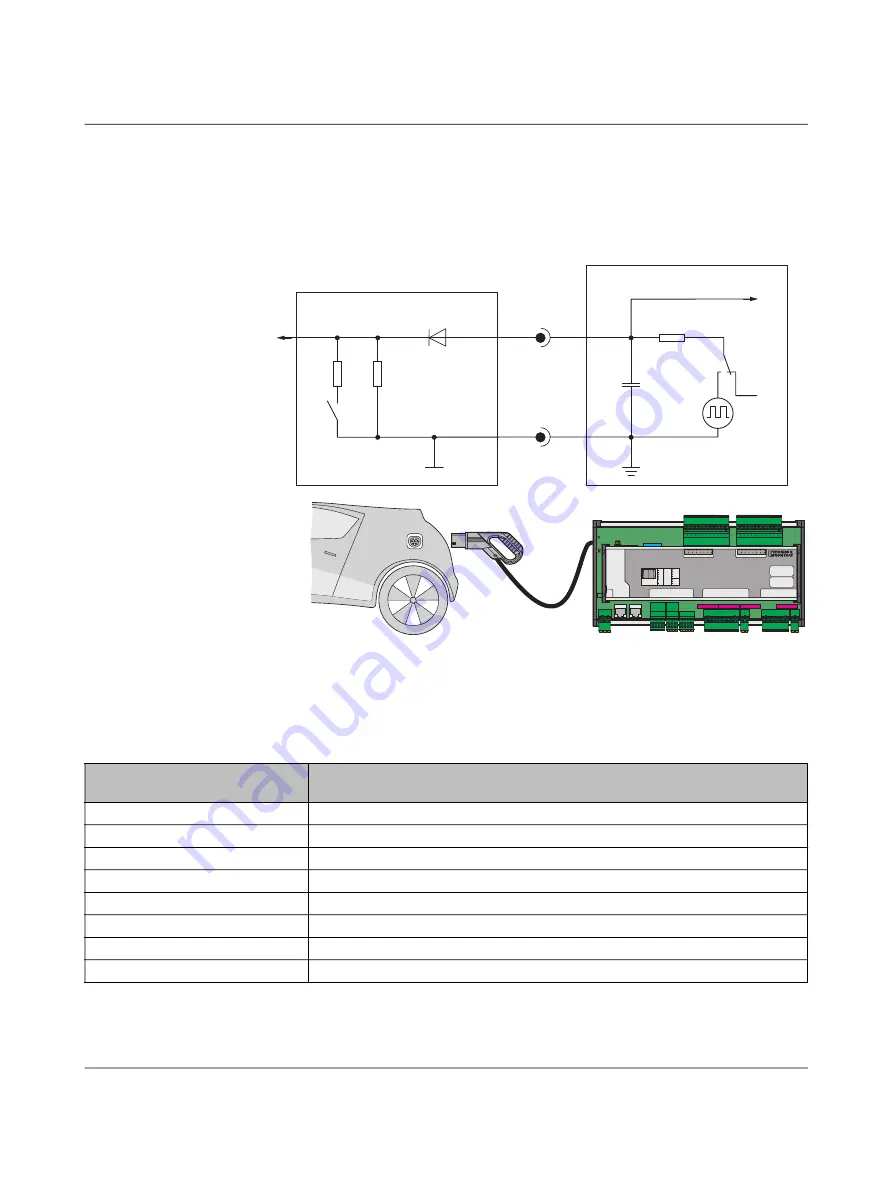
Control Pilot (CP)
The device issues the permissible charging current value via the CP (Control Pilot) signal to
the vehicle as a coded PWM signal. The vehicle indicates the current vehicle status via volt
-
age value Va. Assignment of the permissible charging current value to the pulse width of the
PWM signal and assignment of the voltage value to the vehicle states are defined in
IEC 61851-1, Annex A.
Figure 5
-
2
Control Pilot circuit
The pulse duty factor of the PWM signal at the Control Pilot
specifies to the electric vehicle
the maximum charging current that may be drawn from the mains.
The pulse duty factor of the PWM signal can be adjusted during the charging process, e.g.,
to adapt the charging current to a charging power available from the mains.
S1
R1
12 V
R3
R2
C
S
D1
Control Pilot
V
a
V
b
PWM
S2
CRTL
COM
EV
DC
AC
EV-PLCC-AC1-DC1
Ord. No. 1624130
E
V
C
H
A
R
G
E
C
O
N
T
R
O
L
Power
24 V
X1
X2.1
X2.2
X3
X4
RS232
RS485
CAN
X5
COM
AC Charging
SD
ard
C
Digital IN
X10
SIM
ANT
UL
UM
US
FR
FF
E
RS232-1
RS232-2
RS485-1
RS485-2
CAN
GSM St.
GSM TR.
Error
Plug
Charge
PLC
Error
Plug
Charge
X6
X7
DC Charging
X8
X9
Digital OUT
X11
Table 5
-
2
Controlling the maximum charging current that may be drawn in accordance with IEC 61851-1
Evaluation of nominal pulse duty
factors by the vehicle
Maximum current in accordance with IEC 61851-1 that the vehicle may draw
Pulse duty factor <3%
Charging process is not permitted.
3% ≤ pulse duty factor ≤ 7%
Digital communication; not supported by the controller at this interface.
7% ≤ pulse duty factor ≤ 8%
Charging process is not permitted.
8% ≤ pulse duty factor < 10%
6 A
10% ≤ pulse duty factor ≤ 85%
Available current = (% of pulse duty factor) x 0.6 A
85% < pulse duty factor ≤ 96%
Available current = (% of pulse duty factor - 64) x 2.5 A
96% < pulse duty factor ≤ 97%
80 A
Pulse duty factor >97%
Charging process is not permitted.


