background image

Startup

109745_en_01

PHOENIX CONTACT

31 / 66

6 Startup

6.1

Setting the nominal current

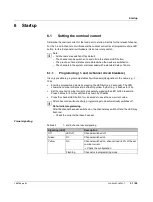
Determine the nominal current of the load prior to startup. Set this for the relevant channel.
For the 1- and 4-channel circuit breakers the nominal current is set (programmed) via LED 

button; for the 2-channel circuit breakers it is set via rotary switch.

Note:

All channels are switched off by default.

The channel can be switched on and off via the channel LED button.

The previous channel states are restored when the device is switched on.

The channels in the system start cascaded with a standard delay of 50 ms.

6.1.1

Programming (1- and 4-channel circuit breakers)

It is only possible to program adjustable circuit breakers (designation in the name, e.g., 1-

10A).

Start the programming mode by pressing the LED button (>2 seconds). The LED 

shows the nominal current set via a flashing yellow rhythm (e.g., 4 flashes for 4 A).

Set the required nominal current by repeatedly pressing the LED button. Example: 

Press 3 times for 3 A, this will then be shown by 3 flashes.

Press the channel LED button for >2 seconds to save the new current value.

After 60 seconds without activity, programming mode automatically switches off.

Note: Initial programming

After the channel has been switched on, the channel may switch off and the LED may 

flash red.

Check the currents that have been set.

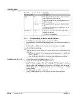
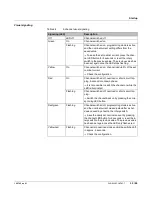
Visual signaling

Table 6

-

1

1- and 4-channel visual signaling

Signaling (LED)

Description

Off

LED off

Channel switched off

Green

On

Channel switched on

Yellow

On

Channel switched on, channel load >80% of the set 

nominal current.

 Check the configuration.

Flashing

Channel is in programming mode

Summary of Contents for 1110984

Page 1: ...User manual CAPAROC System and installation...

Page 2: ...NTACT GmbH Co KG Flachsmarktstra e 8 32825 Blomberg Germany phoenixcontact com 109745_en_01 CAPAROC System and installation This manual is valid for All modules of the CAPAROC system User manual UM EN...

Page 3: ...s 10 2 4 1 CAPAROC power modules 10 2 4 2 CAPAROC circuit breaker modules 11 2 4 3 CAPAROC current rails 12 2 4 4 Housing versions design and dimensions 13 3 Transport and unpacking 21 3 1 Transport 2...

Page 4: ...4DC 1 10A 39 7 1 4 Output process data of CAPAROC E1 12 24DC 1 10A 39 7 1 5 Input process data of CAPAROC E2 12 24DC 2 10A 40 7 1 6 Output process data of CAPAROC E2 12 24DC 2 10A 41 7 1 7 Input proce...

Page 5: ...ology as well as applicable stan dards and other regulations This symbol indicates hazards that could lead to personal injury There are three signal words indicating the severity of a potential injury...

Page 6: ...phoenixcontact net products Here you will find information on each product You can obtain a summary of the technical data by selecting Generate product PDF other important documents can be found on th...

Page 7: ...inets Simply extend the system via the rear current rail Your advantages The customizable standard thanks to a wide range of possible combinations of the fu ture proof modular system Easy operation fo...

Page 8: ...are connected to the right of it The connection between the power module and the individual CAPAROC modules is estab lished via the side bus connectors The internal CAPAROC bus is formed automaticall...

Page 9: ...for a product please visit phoenixcontact net products Go to the page for the relevant product Switch to the Approvals tab The current approvals for the product are listed Observe any notes and restri...

Page 10: ...S R 1115661 power module status reset for supplying the system with the re quired voltage Query system messages via a group message from the module A reset input and an I 80 signal output provide ad...

Page 11: ...E2 12 24DC 1 4A 1115655 Adjustable from 1 4 A CAPAROC E2 12 24DC 2 10A 1110984 Adjustable from 2 10 A adjustable from 1 10 A via bus capable power module 4 channel electronic circuit breakers CAPAROC...

Page 12: ...110989 Rear current rail for distributing the supply voltage with an overall width of 20 HP 123 mm Extension current rails CAPAROC CR EXT4 1110991 Rear current rail for extending the system and distri...

Page 13: ...page 14 Figure 2 7 on page 14 PM S R power module with status reset CAPAROC PM S R Figure 2 8 on page 15 Figure 2 9 on page 15 E1 1 channel circuit breaker CAPAROC E1 12 24DC 1 10A Figure 2 10 on page...

Page 14: ...ACT 109745_en_01 CAPAROC PM PN power module Figure 2 6 Design of CAPAROC PM PN Figure 2 7 Dimensional drawing of CAPAROC PM PN 1 Power LED PWR 4 Diagnostic LEDs 2 RJ45 connections 5 Release 3 Feed in...

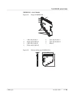
Page 15: ...45_en_01 PHOENIX CONTACT 15 66 CAPAROC PM S R power module Figure 2 8 Design of CAPAROC PM S R Figure 2 9 Dimensional drawing of CAPAROC PM S R 1 Power LED PWR 3 Feed in IN IN 2 Signal connections 4 R...

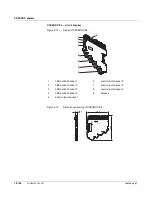
Page 16: ...66 PHOENIX CONTACT 109745_en_01 CAPAROC E1 circuit breaker Figure 2 10 Design of CAPAROC E1 Figure 2 11 Dimensional drawing of CAPAROC E1 1 LED button channel 1 3 Release 2 Load output channel 1 2 3...

Page 17: ...uit breaker Figure 2 12 Design of CAPAROC E2 Figure 2 13 Dimensional drawing of CAPAROC E2 1 LED button channel 1 5 Load output channel 1 2 Rotary switch channel 1 6 Load output channel 2 3 LED button...

Page 18: ...n of CAPAROC E4 Figure 2 15 Dimensional drawing of CAPAROC E4 1 LED button channel 1 6 Load output channel 2 2 LED button channel 2 7 Load output channel 3 3 LED button channel 3 8 Load output channel...

Page 19: ...family 109745_en_01 PHOENIX CONTACT 19 66 CAPAROC PD 0V potential distributor Figure 2 16 Design of CAPAROC PD 0V Figure 2 17 Dimensional drawing of CAPAROC PD 0V 1 IN potential distribution 2 Release...

Page 20: ...CAPAROC system 20 66 PHOENIX CONTACT 109745_en_01...

Page 21: ...ditions During transport observe the specifications regarding humidity and the temperature range 3 2 Storage Suitable storage location The storage location must meet the following requirements Dry Pro...

Page 22: ...CAPAROC system 22 66 PHOENIX CONTACT 109745_en_01...

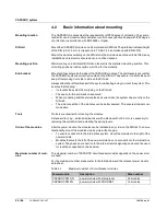
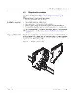
Page 23: ...340 5 1 and IEC 61340 5 1 NOTE Damage to the contacts when tilting Tilting the modules can damage the contacts Place the modules onto the current rail vertically Remove the modules vertically from the...

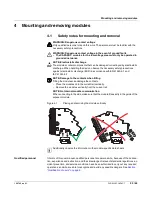
Page 24: ...ing It prevents the system from slipping on the DIN rail The space for the end bracket is secured When connecting additional modules and current rails the system does not slip on the DIN rail The side...

Page 25: ...tional current rail To connect them insert the next current rail in the connection of the preceding one Current rails are available with different overall widths Select the appropriate length for your...

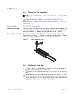
Page 26: ...ving the current rail To remove the current rail from the DIN rail use a screwdriver to release the latching via the slot on the side of the current rail Depending on the current rail used repeat this...

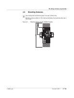
Page 27: ...ONTACT 27 66 4 6 Mounting distances Leave enough space below the system to connect all the cables Maintain a minimum distance of 30 mm above and below to ensure adequate convec tion cooling Figure 4 4...

Page 28: ...CAPAROC system 28 66 PHOENIX CONTACT 109745_en_01...

Page 29: ...Requirements for the power supply Choose a power supply unit that is suitable for the currents in your application The selection depends on the system configuration and the resulting maximum currents...

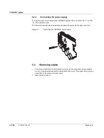
Page 30: ...le The other modules are also automatically supplied with power via the rear current rail Figure 5 1 Connecting the CAPAROC power supply 5 3 Removing cables To remove a cable from the terminal point p...

Page 31: ...tion in the name e g 1 10A Start the programming mode by pressing the LED button 2 seconds The LED shows the nominal current set via a flashing yellow rhythm e g 4 flashes for 4 A Set the required nom...

Page 32: ...rotary switch down step by step so that it approaches the operating current that is currently flowing This will enable you to find the appropriate setting for the chan nel The channel LED flashes gree...

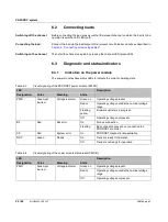
Page 33: ...ration Red On Channel switched off overload or short circuit trip ping 5 second cool down phase It is not possible to switch the channel on while the LED is illuminated Flashing Channel switched off o...

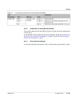
Page 34: ...aling of the PROFINET power module PM PN LED Description Designation Color Meaning State PWR Green yel low red Voltage indicator Green on Operating voltage present Red on Operating voltage outside the...

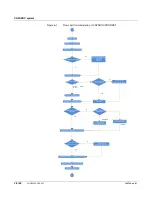
Page 35: ...ers on page 31 and Section Programming 2 channel circuit breakers on page 32 6 3 3 Flow chart for startup The flow chart illustrates typical startup It does not include all the parameterization option...

Page 36: ...nstromeinstellung Pro net manuell am Ger t nein ja Kon guration der IP Parameter im Engineering Gesamtsystem oder einzelne Kan le ja Slot 0 Subslot 2 Strom Parametriersperre Slot X 1 16 Subslot 1 Loka...

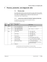
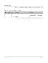
Page 37: ...ystem depends on the temperature derating The value range that can be represented does not correspond to the permissible operating voltage range Table 7 1 Input process data slot 0 subslot 2 Byte offs...

Page 38: ...ut down by a short circuit or overload back on The command is issued once by setting bit 0 to 1 To send another reset com mand first set bit 0 to 0 Then set bit 0 to 1 again Table 7 2 Output process d...

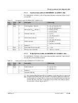
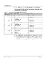
Page 39: ...he rest of the output process data for this module is also deemed valid as soon as either of the two flags is set to 1 Table 7 3 Input process data of CAPAROC E1 12 24DC 1 10A Byte offset Data type Bi...

Page 40: ...1 warning active 2 Overload channel 1 0 no error 1 overload shutdown 3 Short circuit channel 1 0 no error 1 short circuit shutdown 4 Defect channel 1 0 no defect 1 hardware is defective 5 7 Reserved...

Page 41: ...tput channel The signal for switch on or switch off must be applied for at least 1500 ms Internally only one validity flag is available per module The rest of the output process data for this module i...

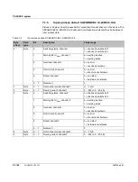
Page 42: ...1 warning active 2 Overload channel 1 0 no error 1 overload shutdown 3 Short circuit channel 1 0 no error 1 short circuit shutdown 4 Defect channel 1 0 no defect 1 hardware is defective 5 7 Reserved...

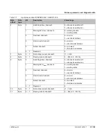
Page 43: ...inal current channel 3 1 10 A 8 Byte 0 7 Flowing current channel 3 0 255 0 25 5 A 9 Byte 0 Switching status channel 4 0 channel is switched off 1 channel is switched on 1 Warning 80 INom channel 4 0 w...

Page 44: ...lidity flag is available per module The rest of the output process data for this module is also deemed valid as soon as either of the two flags is set to 1 Table 7 8 Output process data of CAPAROC E4...

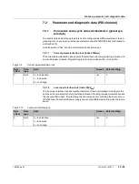
Page 45: ...l circuit breaker modules Programming is performed via the switch or the button 7 2 1 2 Local user interface lock index 000Chex The local user interface lock ensures that operation of the circuit brea...

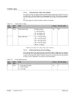
Page 46: ...operating mode of the device after the voltage reset In indepen dent operation the channels that were switched on prior to the voltage reset are switched on again In the case of the Wait for fieldbus...

Page 47: ...part of the startup parameterization For example the WRREC block is used to write to this index Only application parameters are reset with this index The communication parame ters such as the station...

Page 48: ...mand must be issued to the slot that corresponds to the module position in the system The subslot is always 1 The nominal current is only adopted if the rotary switch is in the RC position see Sectio...

Page 49: ...e system The subslot is always 1 Table 7 15 Local nominal current programming lock Byte offset Data type Data Access Default setting 0 Byte 0 channel 1 lock inactive r w 0 1 channel 1 lock active 2 no...

Page 50: ...counter for just one channel the write command must be 4 bytes long The counter to be reset must include a 0 in the byte Example Clear error counter for channel 1 and retain error counter for channel...

Page 51: ...AROC PM PN PROFINET power module has a web server that is switched off by default Following activation via PROFINET it can be reached via port 80 using the previously as signed IP address The web serv...

Page 52: ...CAPAROC system 52 66 PHOENIX CONTACT 109745_en_01...

Page 53: ...They may be blocked by a firewall If necessary disable the firewall on your PC Interface to other systems Interface to other systems 8 2 Preparing the update Start the PC WORX FIRMWARE UPDATER Click o...

Page 54: ...CAPAROC system 54 66 PHOENIX CONTACT 109745_en_01 Figure 8 1 PC WORX FIRMWARE UPDATER...

Page 55: ...pter 2 Select the storage location TFTP root directory and the firmware file 3 Click on Standard settings 4 Under General Time after which the device is available after update ms change the value to 1...

Page 56: ...user interface 8 3 Performing the update Search for devices Use the icon Network Scan to start searching for devices The device must have a valid IP address and subnet mask If necessary enter a valid...

Page 57: ...FIRMWARE UPDATER start update Complete update Make sure that the update process is not interrupted e g due to interrupted power sup ply The green progress bar indicates the download progress of the f...

Page 58: ...k after the update If the update was successful the device is highlighted in green The Update Info is Ok Check that firmware 0 00 01 test firmware is displayed This indicates definitively that the upd...

Page 59: ...our application with a new module See Section 4 5 Replacing a module If necessary connect the supply and the I O devices See Section 5 Connecting or re moving cables Observe the device type To ensure...

Page 60: ...bserve the storage and transport requirements See Section 3 Transport and un packing The device is not used anymore Device disposal Do not dispose of the device with household waste it should instead...

Page 61: ...sional drawing of CAPAROC PM S R 15 Figure 2 10 Design of CAPAROC E1 16 Figure 2 11 Dimensional drawing of CAPAROC E1 16 Figure 2 12 Design of CAPAROC E2 17 Figure 2 13 Dimensional drawing of CAPAROC...

Page 62: ...ORX FIRMWARE UPDATER Preferences dialog 55 Figure 8 3 PC WORX FIRMWARE UPDATER user interface 56 Figure 8 4 PC WORX FIRMWARE UPDATER device search 56 Figure 8 5 PC WORX FIRMWARE UPDATER start update 5...

Page 63: ...dule PM PN 34 Table 6 4 Visual signaling of the power module status reset PM S R 34 Section 7 Table 7 1 Input process data slot 0 subslot 2 37 Table 7 2 Output process data slot 0 subslot 2 38 Table 7...

Page 64: ...able 7 14 Nominal current setting 48 Table 7 15 Local nominal current programming lock 49 Table 7 16 Channel outputs 49 Table 7 17 Error counter 50 Table 7 18 Only clear error counter for channel 1 50...

Page 65: ...f the products in your specific application in particular with regard to observ ing the applicable standards and regulations All information made available in the technical data is supplied without an...

Page 66: ...tion It can be downloaded at phoenixcontact net products Subsidiaries If there are any problems that cannot be solved using the documentation please contact your Phoenix Contact subsidiary Subsidiary...

Page 67: ......
Page 68: ...IX CONTACT 2021 10 19 109745_en_01 Order No 01 PHOENIX CONTACT GmbH Co KG Flachsmarktstra e 8 32825 Blomberg Germany Phone 49 5235 3 00 Fax 49 5235 3 41200 E mail info phoenixcontact com phoenixcontac...

Reviews: