background image

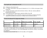
 Funciones de visualización y advertencia

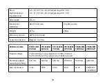
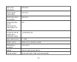
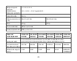
LED

Estado

Función

Encendido

Controlador conectado a la batería, detección nocturna

Destello

Controlador conectado a la batería, detección diurna

Apagado

Sin conexión a batería

Encendido

Desconexión de carga por voltaje alto/bajo (LVD/HVD)

Destello

Exceso de corriente de carga

Apagado

Carga correcta

Encendido

Atenuación debida a LVD/HVD

Apagado

Sin atenuación

Todos los 

LED

Verde->Rojo-

>Verde->

Programación

37

Summary of Contents for CIS-N-LED 1050 mA

Page 1: ...Phocos CIS N LED 350 mA 600 mA 700 mA 1050 mA 1400 mA 2800 mA Bedienungsanleitung User Manual Manual de Instrucciones Guide de l utilisateur Manual do Usuário 用户说明书 CID 181817210 ...

Page 2: ...CONTENTS Bedienungsanleitung User Manual Manual de Instrucciones Guide de l utilisateur Manual do Usuário 用户说明书 1 16 17 31 32 47 48 63 64 79 80 93 ...

Page 3: ...ges Ladeverfahren Haupt Boost Ausgleichs u Erhaltungsladung für flüssigsäure Batterien 3 stufiges Laden Haupt Boost u Erhaltungsladung für GEL Batterien Signaleingang zum Anschluss von Bewegungsmelder PIR Allgemeine Sicherheitshinweise Diese Anleitung enthält wichtige Anweisungen für die Installation den Anschluss und sicheren Betrieb Bevor Sie mit der Installation beginnen lesen Sie bitte sorgfäl...

Page 4: ...echten Kontaktes mit der Möglichkeit einer Überhitzung und eventuell weiterführenden Schäden Bitte installieren Sie eine Sicherung oder einen Stromkreisunterbrecher in der Nähe der Batterie bevor Sie den Regler installieren oder einstellen Hochspannungsrisiken Berühren Sie niemals spannungsführende Bauelemente Kabel etc die nicht isoliert sind Vorsicht Gefahr eines elektrischen Schlags Arbeiten Si...

Page 5: ... Erdung Verbinden Sie die Kabel in der angezeigten Reihenfolge 1 2 3 4 5 6 7 um Installationsfehler zu vermeiden Um Spannung an den Kabeln zu vermeiden verbinden Sie zuerst die Kabel am Laderegler dann an der Batterie Modul oder Last Stellen Sie sicher dass die Kabellänge zwischen Batterie und Laderegler so kurz wie möglich ist Maximale Kabellänge vom Laderegler zu den LEDs 2 m Beachten Sie dass d...

Page 6: ...4 Sich erung ...

Page 7: ...schwarz Positiver Batterieanschluss BATTERY AWG 13 2 5 mm2 rot Negativer Panelanschluss COMMON AWG 13 2 5 mm2 schwarz Positiver Panelanschluss SOLAR AWG 13 2 5 mm2 gelb PIR Eingang PIR AWG 24 0 25mm schwarz Achtung Die negative LED Leitung darf nicht mit der Erde oder Masse verbunden werden Die Leitungen zu den LEDs dürfen nur an die LEDs und an nichts anderes angeschlossen werden 5 ...

Page 8: ...nken Laderegler ist mit der Batterie verbunden Tag erkannt Aus Keine Batterie verbunden An Tiefentladeschutz Überspannungsabschaltung LVD HVD Blinken Last Überstrom Aus Last OK An Dimmen aufgrund von LVD HVD Tiefentladeschutz Überspannungsabschaltung Aus Kein Dimmen Alle LEDs Grün Rot Grün Programmierung 6 ...

Page 9: ... externem Bewegungsmelder Dimm Funktion Ausgangs Verhalten Kein Dimmen Dimmen an Last aus Zeitschalter 1 An An Aus Zeitschalter 2 An Aus Nicht verfügbar Die Einstellungen der Timerfunktionen und für das Dimmen können mittels CIS CU LCD Infrarot Fernbedienung oder MXI IR Infrarot USB Adapter und CISCOM PC Programm vorgenommen werden PIR Eingang 0 0 5 V Aus 4 30 V Ein Zum Anschluss eines Bewegungsme...

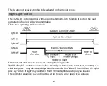
Page 10: ...die vom Bewegungsmelder bestimmte Zeitdauer auf Volllicht umgeschaltet Nachtlichtfunktion Der CIS N LED Laderegler verfügt über eine hochentwickelte Nachtlichtfunktion Er kontrolliert den Lastausgang bei Nacht und ist vielseitig programmierbar Es stehen 3 Modi zur Verfügung Standard Laderegler Modus Abend bis Morgendämmerungs Modus und Abend Morgen Modus 8 ...

Page 11: ...entsprechende Programmierung den lokalen Lichtverhältnissen und der verwendeten Solaranlage angepasst werden Testfunktion Das Drücken der Test Taste an der Fernbedienung CIS CU LCD schaltet den LED Treiber für eine Minute an Anmerkung Sollte das Drücken der Taste einen Lastabwurf LVD Tiefentladungsschutz SOC Überstrom verursachen wird die Last sofort ausgeschaltet Sicherheitsfunktionen Solar Einga...

Page 12: ...2 Kurzschluss 3x 20x Nennstrom 3 Die Batterie muss mittels Sicherung geschützt werden oder sie kann durch einen Kurzschluss dauerhaft geschädigt werden Hinweis Es empfiehlt sich eine Sicherung zu verwenden deren Ampere Stärke den Nennstrom des Ladereglers entspricht z B benötigt der CIS N LED 10 A eine 10 A Sicherung 4 Ein Rückstrom durch das Solarpanel wird durch einen Serien MOSFET verhindert Di...

Page 13: ... 25 22 50V bis 11 83 23 63V SOC3 11 38 22 72V bis 11 89 23 78V SOC4 11 51 23 02V bis 11 96 23 92V SOC5 11 64 23 28V bis 12 02 24 04V SOC6 Spannungsgesteuert LVD Abschaltung bei einer bestimmten Spannung zwischen 11 00 22 00 V und 11 9 23 8 V Schritt 0 1 0 2V Anmerkung Die Batteriespannung muss für mehr als 2 Minuten unter dem eingestellten Wert liegen bevor der LVD auslöst Werkseinstellungen Sie k...

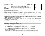
Page 14: ...16 V 1 Zeitschalter 1 Abendstunden 0 h Zeitschalter 1 Morgenstunden 0 h Zeitschalter 2 Abendstunden 0 h Zeitschalter 2 Morgenstunden 0 h 1 hier handelt es sich um Leerlaufspannung Tagesniveau Nachtniveau 1 5 3 0 V Technische Daten Anmerkung Die zwei Spannungsbereiche vor und nach dem Schrägstrich gelten jeweils für 12 V bzw 24 V Systeme 12 ...

Page 15: ...ng 14 4 28 8 V 25 C 0 5 Std täglich Boostladung 14 4 28 8 V 25 C 2 Std Aktivierung Batteriespannung 12 3 24 6V Ausgleichsladung 14 8 29 6 V 25 C 2 Std Aktivierung Batteriespannung 12 1 24 2V mindestens alle 30 Tage Tiefentladeschutz Abschaltspannung 11 00 12 02 22 00 24 04 V bei SOC 11 0 22 0 11 9 23 8 V bei Spannung einstellbarer Schritt 0 1 0 2 V Wiedereinschalt spannung 12 8 25 6 V Überspannung...

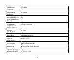
Page 16: ...aturkompen sation Ladespannung 4 2 mV K 2 V Zelle Max Eigenverbrauch 5 8 mA Erdung Negative Erdung Umgebungstem peratur 40 bis 60 C Max Höhe 4 000 m ü NN Batterietyp Blei GEL AGM flüssig Einstellbereich Abend Morgen stunden Tag Nachter kennung 0 15 Std 0 14 Std 2 5 10 0 V 5 0 20 0 V einstellbarer Schritt 0 5 1 0 V 4 0 11 5 V 8 0 23 0 V einstellbarer Schritt 0 5 1 0 V Kabellänge 20 cm 14 ...

Page 17: ...S N LED 600 mA CIS N LED 700 mA CIS N LED 1050 mA CIS N LED 1400 mA CIS N LED 2800 mA Ausgangsspannung 15 V bis 49 V für 12 V System 5 bis 15 LEDs in Serie 30 V bis 49 V für 24 V System 10 bis 15 LEDs in Serie Nominaler Ausgangsstrom pro String 350 mA 600 mA 700 mA 1050 mA 1400 mA 2800 mA Maximale Ausgangsleistung 15 W 25 W 30 W 45W 60 W 60W 12V 120W 24V Dimm Niveau 0 100 einstellbare Schrittweite...

Page 18: ...r wie im Handbuch beschriebene Verwendung entstehen oder wenn die Empfehlungen des Batterieherstellers missachtet werden Der Hersteller haftet nicht wenn Reparaturen oder Kundendienst von nicht autorisierten Personen durchgeführt wurden bei unsachgemäßem Gebrauch falscher Installation oder falscher Systemauslegung Änderungen jeder Art vorbehalten selbige können ohne vorherige Benachrichtigung am C...

Page 19: ...stage charging main boost equalization float for flooded battery 3 stage charging main boost float for sealed battery Input signal for motion sensor PIR General Safety Information This manual contains important installation set up and safety operating instructions Please read the instructions and warnings in this manual carefully before beginning any installation Please do not disassemble or attem...

Page 20: ... before installing or adjusting the controller High voltage risks Never touch any electrical conductors in order to avoid electrical shock Never work on live energized electrical equipment When working around a battery do not allow tools to bridge the battery terminals or short circuit any part of the battery Use only tools with insulated handles Operation of this device may produce high voltage w...

Page 21: ...s first connect the wire to the controller then to the battery panel or load Make sure the wire length between battery and controller is as short as possible Maximum cable length from charge controller to LEDs 2m Be aware that the negative terminals of CIS N LED are connected together and therefore have the same electrical potential If any grounding is required always do this on the negative wires...

Page 22: ...20 Fuse ...

Page 23: ...ative battery terminal COMMON AWG 13 2 5 mm2 Black Positive battery terminal BATTERY AWG 13 2 5 mm2 Red Negative panel terminal COMMON AWG 13 2 5 mm2 Black Positive panel terminal SOLAR AWG 13 2 5 mm2 Yellow DIM Override input PIR AWG 24 0 25mm Black Warning The wires to the LEDs must not be connected to ground or anything else than the LEDs 21 ...

Page 24: ...ted to battery night detected Flash Controller connected to battery day detected Off No battery connected On Load low high voltage disconnect LVD HVD Flash Load overcurrent Off Load OK On Dimming due to of LVD HVD Off No dimming All LED Green Red Green Programming 22 ...

Page 25: ...tion output logics No dimming Dimming on Load off Timer 1 on on off Timer 2 on off N A The timer and dimming settings can be adjusted using the CIS CU LCD Infrared remote control or MXI IR Infrared to USB adapter and CISCOM PC program PIR Dimming override input 0 0 5 V Off 4 30 V On Input for a signal from a motion sensor PIR to override the dimming and set the light to full brightness in case a p...

Page 26: ...ting modes available Standard Controller Dusk to Dawn and Evening Morning modes Middle of night is detected automatically as the midpoint between dusk and dawn no setting of a clock is required It may take several days until the controller has learned the middle of the night precisely Middleofnight maybedifferent from12 00 midnight depending onyour location The controller recognizes day and night ...

Page 27: ...the button causes a load disconnect event LVD SOC overcurrent the load will be switched off immediately Safety Features Solar terminal Battery terminal LED output PIR input Reverse polarity Protected 1 Protected 1 N A Protected Short circuit 2 Protected Protected 3 Not protected Protected Overcurrent N A N A N A N A Reverse current Protected 4 N A N A N A Overvoltage Max 50 V 5 Max 36 V Switches o...

Page 28: ...serial MOSFET This function is tested and activated approx one time in 1min 5s 5 The solar panel voltage should not exceed this limit for a longer period of time as surge protection is present by varistor WARNING The combination of different error conditions may cause damage to the controller Always remove the error before you continue connecting the controller Low Voltage Disconnect Function LVD ...

Page 29: ...unit CIS CU LCD See CIS CU LCD manual for details Factory settings Load mode Standard controller night light off Low voltage disconnect SOC4 Battery type GEL Dimming value 50 Night detect level 8 16 V 1 Timer 1 evening hours 0 h Timer 1 morning hours 0 h Timer 2 evening hours 0 h Timer 2 morning hours 0 h 1 PV panel open circuit voltage Day level night level 1 5 3 0 V 27 ...

Page 30: ...ecognition Max charge current 10 A 15 A 50 C 20 A 30 A 50 C Float charge 13 8 27 6 V 25 C Main charge 14 4 28 8 V 25 C 0 5 h daily Boost charge 14 4 28 8 V 25 C 2 h Activation battery voltage 12 3 24 6 V Equalization 14 8 29 6 V 25 C 2 h Activation battery voltage 12 1 24 2 V at least every 30 days Deep discharge protection Cut off voltage 11 00 12 02 22 00 24 04 V by SOC 11 0 22 0 11 9 23 8 V by ...

Page 31: ...rotection by varistor 50 V Temperature compensation Charge voltage 4 2 mV K 2 V cell Max self consumption 5 8 mA Grounding Negative grounding Ambient temperature 40 to 60 C Max altitude 4 000 m above sea level Battery type Lead acid GEL AGM flooded Adjustment range Evening morning 0 15 h 0 14 h 29 ...

Page 32: ... AWG 13 2 5 mm2 Type of protection IP68 1 5 m 72 h LED driver data CIS N LED 350 mA CIS N LED 600 mA CIS N LED 700 mA CIS N LED 1050 mA CIS N LED 1400 mA CIS N LED 2800 mA Output voltage 15 V to 49 V for 12 V system 5 to 15 LEDs in series 30 V to 49 V for 24 V system 10 to 15 LEDs in series Nominal output current per string 350 mA 600 mA 700 mA 1050 mA 1400 mA 2800 mA Max load power 15 W 25 W 30 W...

Page 33: ...h temperatures Liability Exclusion The manufacturer shall not be liable for damages especially to the battery caused by use other than as intended or as mentioned in this manual or if the recommendations of the battery manufacturer are neglected The manufacturer shall not be liable if there has been service or repair carried out by any unauthorized person unusual use wrong installation or bad syst...

Page 34: ...or exterior de temperatura de LED para mantener baja la temperatura de LED 4 fases de carga para baterías con electrolito líquido principal de floración rápida de compensación 3 fases de carga para baterías selladas principal rápida flotación Entrada de detección de movimiento PIR Información general de seguridad Este manual contiene instrucciones de funcionamiento importantes de instalación confi...

Page 35: ...ue que todas las conexiones de los cables se han hecho apropiadamente y que están debidamente aislados y que tanto agua o humedad no pueden ingresar con el fin de evitar malas conexiones o perdidas que podrían provocar un calentamiento excesivo o daños mayores Por favor instale un fusible o disyuntor cerca de la batería antes de instalar o ajustar el controlador Riesgos de voltaje alto Nunca toque...

Page 36: ...sa para su salud Sello CE El producto tiene la conformidad CE Conexión y puesta a tierra Conecte los cables en el orden indicado 1 2 3 4 5 6 7 para evitar fallas de la instalación Para evitar el voltaje en los cables primero conecte el cable al controlador luego a la batería panel o carga Asegúrese de que el cable entre la batería y el controlador sea lo más corto posible Longitud máxima de cable ...

Page 37: ... Negro Terminal positivo de la batería BATTERY AWG 13 2 5 mm2 Rojo Terminal negativo del módulo COMMON AWG 13 2 5 mm2 Negro Terminal positivo del módulo SOLAR AWG 13 2 5 mm2 Amarillo DIM Entrada de desactivación PIR AWG 24 0 25mm Negro Advertencia Los cables negativos de los LED no deben estar conectados a tierra No se permite que los cables que conectan a los LED se conecten a otro lado 35 ...

Page 38: ...36 Fusi ble ...

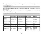
Page 39: ...a Destello Controlador conectado a la batería detección diurna Apagado Sin conexión a batería Encendido Desconexión de carga por voltaje alto bajo LVD HVD Destello Exceso de corriente de carga Apagado Carga correcta Encendido Atenuación debida a LVD HVD Apagado Sin atenuación Todos los LED Verde Rojo Verde Programación 37 ...

Page 40: ...ver del LED a proporcionar la máxima corriente nominal de salida 100 de brillo A ser usada con un detector de movimiento externo Función de atenuación lógica de salidad Sin atenuación Atenuación encendida Carga apagada Temporizador 1 encendido encendido apagado Temporizador 2 encendido apagado N C Los ajustes al Temporizador Timer y al Atenuador Dimer se los puede realizar con el CIS CU LCD contro...

Page 41: ...el de iluminación mínimo sufici ente para que las personas puedan orientarse y para ahorrar energía Cuando detecta movimiento la intensidad de luz cambia al 100 La duración de la activación se ajusta en el detector de movimiento Función de luz nocturna El controlador CIS N LED cuenta con una sofisticada función de luz nocturna Controla la salida de carga nocturna y es ampliamente programable Hay t...

Page 42: ...ontrolador reconoce el día y la noche sobre la base del voltaje de circuito abierto del módulo solar El umbral día noche se puede modificar de acuerdo a las condiciones locales y al módulo solar utilizado Función de prueba Al presionar el botón de prueba en la CU unidad de control se enciende el terminal de carga durante 1 minuto Si al presionar el botón se genera un evento de desconexión de carga...

Page 43: ...de carga por PWM si se produce un exceso de temperatura y apaga la carga si la temperatura alcanza el nivel alto N C 1 UPanel UBatería se limita a 40 V 2 Cortocircuito 3x 20x de la corriente nominal 3 La batería debe estar protegida por fusibles o se dañará en forma permanente Observacion Es recommendable usar un fusible cuyo amperaje corresponda a la corriente nominal del controlador de carga por...

Page 44: ...2 00 V hasta 11 70 V 23 40 V SOC1 11 12 V 22 24 V hasta 11 76 V 23 52 V SOC2 11 25 V 22 50 V hasta 11 83 V 23 63 V SOC3 11 38 V 22 72 V hasta 11 89 V 23 78 V SOC4 11 51 V 23 02 V hasta 11 96 V 23 92 V SOC5 11 64 V 23 28 V hasta 12 02 V 24 04 V SOC6 Tensión controlada LVD Se desconecta entre una tensión fija entre 11 0 V 22 0 V y 11 9 V 23 8 V Salto 0 1 V Nota el voltaje de la batería debe estar po...

Page 45: ...o de batería Gel Valor de atenuación 50 Nivel de luz nocturna 8 V 1 Temporizador 1 de horas de la tarde 0 h Temporizador 1 de horas de la mañana 0 h Temporizador 2 de horas de la tarde 0 h Temporizador 2 de horas de la mañana 0 h 1 Aquí hay voltaje de circuito abierto del panel nivel diurno nivel nocturno 1 5 3 0 V 43 ...

Page 46: ...0 A 30 A 50 C Carga de flotación 13 8 27 6 V 25 C Carga principal 14 4 28 8 V 25 C 0 5 h diarias Carga rápida 14 4 28 8 V 25 C 2 h Activación voltaje de la batería 12 3 24 6 V Ecualización 14 8 29 6 V 25 C 2 h Activación voltaje de la batería 12 1 24 2 V al menos cada 30 días Protección contra descarga total Tensión de desconexión 11 00 12 02 V 22 0 24 04 V en caso de SOC 11 00 12 00 V 22 0 24 00 ...

Page 47: ...e máx del panel Protección de sobrevoltaje con varistor 50 V Compensación de temperatura Voltaje de carga 4 2 mV K per cell Máx autoconsumo 5 8 mA Puesta a tierra Puesta a tierra negativa posible Temperatura ambiente 40 a 60 C Altitud 4 000 m sobre el nivel del mar Tipo de batería plomo ácido GEL AGM electrolito líquido 45 ...

Page 48: ...P68 1 5 m 72 h Datos del controlador LED CIS N LED 350 mA CIS N LED 600 mA CIS N LED 700 mA CIS N LED 1050 mA CIS N LED 1400 mA CIS N LED 2800 mA Voltaje de salida 15 V a 49 V para el sistema de 12 V 5 a 15 LEDs conectados en serie 30 V a 49 V para el sistema de 24 V 10 a 15 LEDs conectados en serie Corriente nominal de salida por cadena 350 mA 600 mA 700 mA 1050 mA 1400 mA 2800 mA Potencia de car...

Page 49: ...a temperaturas más altas del objeto Exclusión de responsabilidad El fabricante no será responsable por los daños especialmente de la batería provocados por un uso diferente del previsto o mencionado en este manual ni por la falta de cumplimiento de las recomendaciones del fabricante de la batería El fabricante no será responsable en caso de reparaciones o servicios realizados por parte de personas...

Page 50: ... températures des tensions de charge Détecteur externe de température LED afin de maintenir basse la température des LED 4 modes de recharge tension principale de boostage d égalisation flottante pour batteries liquides 3 modes de recharge tension principale de boostage flottante pour batteries GEL Entrée pour détecteur de mouvement infrarouge passif PIR Informations générales sur la sécurité Le p...

Page 51: ...llation et l entretien Avant de procéder à l installation du système photovoltaïque ou d y effectuer une intervention veuillez d abord déconnecter les modules photovoltaïques solaires du régulateur de charge pour éviter tout dommage à celui ci Veuillez vous assurer que tous les câbles fils sont dûment raccordés et isolés et que ni eau ni humidité ne peut pénétrer afin d éviter de mauvais brancheme...

Page 52: ...teur et de chargement Assurez vous que les câbles sont toujours branchés sur la borne adéquate Une décharge électrique peut être mortelle En règle générale une décharge électrique peut être dangereuse pour votre santé Étiquetage CE Ce produit est conforme aux normes CE Raccordement et mise à la terre Connectez les fils dans l ordre indiqué 1 2 3 4 5 6 7 afin d éviter des erreurs d installation Afi...

Page 53: ...e LED positive AWG 24 0 2 mm2 Rouge Borne négative de la batterie COMMON AWG 13 2 5 mm2 Noir Borne positive de la batterie BATTERY AWG 13 2 5 mm2 Rouge Borne négative du panneau solaire COMMON AWG 13 2 5 mm2 Noir Borne positive du panneau solaire SOLAR AWG 13 2 5 mm2 Jaune Entrée de contournement de gradation PIR AWG 24 0 25mm Noir Avertissement Les conducteurs négatifs des LED ne doivent pas être...

Page 54: ...52 Fusi ble ...

Page 55: ...gulateur connecté à la batterie détection de jour Arrêt Batterie non connectée Marche Protection de décharge profonde de surtension LVD HVD Clignote Surintensité de charge Arrêt Charge OK Marche Gradation par protection de décharge profonde de surtension Arrêt Pas de gradation Toutes les LED Vertes Rouges Vertes Programmation en cours 53 ...

Page 56: ...mouvement Fonction Variateur logique de sortie Pas de gradation Gradation Arrêt charge Minuteur 1 Marche Marche Arrêt Minuteur 2 Marche Arrêt Non disponible Les paramètres du minuteur et du gradateur peuvent être ajustés au moyen soit de la CIS CU LCD unité de commande infrarouge à distance soit du MXI IR adaptateur entre signal infrarou ge et USB et du CISCOM programme informatique Entrée de cont...

Page 57: ...n jour nuit Le régulateur CIS N LED est équipé d une fonction avancée jour nuit qui commande la charge pendant la nuit et est intégralement programmable Il existe 3 modes différents Standard du crépuscule à l aube et soirée matin Le milieu de la nuit est automatiquement identifié comme point central entre le crépuscule et l aube aucune configuration n est requise Plusieurs jours peuvent être néces...

Page 58: ... sur la touche test de l unité de commande vous mettez sous tension la borne de charge pendant 1 minute Si en appuyant sur la touche vous déclenchez un délestage LVD SOC surintensité la charge est immédiatement mise hors tension Caractéristiques de sécurité Borne panneau Borne batterie Sortie LED Entrée PIR Polarité inversée Protégée 1 Protégée 1 Non disponible Protégée Court circuit 2 Protégée Pr...

Page 59: ...mmagée irrémédiablement Remarque Il est recommandé d utiliser un fusible dont l ampérage correspond au courant nominal du régulateur de charge Par exemple le CIS N LED 10 A a besoin d un fusible de 10 A 4 Le courant inversé qui traverse le panneau solaire est bloqué par MOSFET de série Cette fonction est testée et activée environ une fois par minute 5 s 5 La tension du panneau solaire ne doit pas ...

Page 60: ...se entre 11 0 V 22 0 V et 11 9 V 23 9 V par palier de 0 1 V Remarque les deux niveaux de tension se trouvant avant et après le sont respectivement valables pour des appareils de 12 V et 24 V Remarque Si la tension de la batterie est plus basse que la position de réglage pendant plus de 2 minutes la tension se déclenche Paramètres d usine par défaut Vous pouvez configurer le régulateur CIS N LED vi...

Page 61: ...veau du jour niveau de la nuit 1 5 V Caractéristiques techniques Caractéristiques techniques CIS N LED 350 mA CIS N LED 600 mA CIS N LED 700 mA CIS N LED 1050 mA CIS N LED 1400 mA CIS N LED 2800 mA Tension nominale 12 24 V reconnaissance automatique Courant de charge max 10 A 15 A 50 C 20 A 30 A 50 C Charge d entretien 13 8 27 6 V 25 C Charge principale 14 4 V 28 8 25 C 0 5 h quotidiennement 59 ...

Page 62: ...V au moins tous les 30 jours Protection de décharge profonde Tension de coupure 11 00 12 02 V 22 00 24 04 V SOC 11 0 12 0 V 22 0 24 0 V tension Niveau de reconnexion 12 8 25 6 V Protection surtension 15 5 31 0 V Protection sous tension 10 5 21 0 V Tension max panneau solaire protection surtension par varistance 50 V Compensation thermique 4 2 mV K par cellule 60 ...

Page 63: ...u de la mer Type de batterie Plomb acide GEL AGM liquide Gamme de réglage Heures de soirée matinée Détection nuit jour 0 15 h 0 14 h 2 5 10 V 4 11 5 V par paliers de 0 5 V Longueur des fils 20 cm Dimensions L x h x l 82 x 97 x 20 mm 92 x 99 x 22 mm Poids 210 g 250 g Section transversale des fils AWG 13 2 5 mm2 Type de protection IP68 1 5 m 72 h 61 ...

Page 64: ...it max 15 W 25 W 30 W 45W 60 W 60W 12V 120W 24V Niveau de gradation 0 100 par paliers de 10 Entrée PIR 4 V à 30 V selon la borne négative de la batterie 0 7 mA protection limitée à 50 V 12 V 15 24 V 5 8 LEDs en série Lorsque le régulateur est monté sur une surface qui maintient la température du boîtier à 50 C maximum pendant que la batterie est en chargement et qu aucun courant n est utilisé par ...

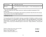
Page 65: ...oi ou si les recommandations du fabricant de la batterie ne sont pas respectées Le fabricant ne pourra être tenu responsable en cas de maintenance ou de réparation réalisée par toute personne non habilitée d utilisation inappropriée d installation incorrecte ou d une mauvaise conception du système Susceptible d être modifié sans préavis Version 20150130 Fabriqué dans l un des pays suivants Allemag...

Page 66: ...radeníveis decarga Sensor LED externo de temperatura para manter a temperatura de LED baixa Carga em 4 estágios principal rápida equalização flutuante para bateria ventilada carga em 3 estágios principal rápida flutuante para bateria selada Entrada para sensor de movimento PIR Informações gerais de segurança Este manual contém instruções de instalação configuração e operação importantes Leia as in...

Page 67: ...to poderá resultar em mal contato que resultaria em aquecimento excessivo com danos consequentes Instale um fusível ou disjuntor próximo da bateria antes de instalar ou ajustar o controlador Riscos de tensão elevada Perigo de tensão elevada Evite qualquer contato com os condutores de forma a prevenir choque elétrico Nunca execute instalação ou manutenção em equipamento energizado Quando tiver de m...

Page 68: ...itar falhas de instalação Para evitar qualquer tensão nos condutores primeiro conecte o condutor ao controlador depois à bateria painel ou carga Certifique se de que o comprimento do condutores entre a bateria e o controlador seja o menor possível Comprimento máximo de condutores 2m Esteja ciente que os terminais negativos CIS N LED estão conectados e por isto têm o mesmo potencial elétrico Caso s...

Page 69: ...67 Fusí vel ...

Page 70: ...reto Terminal positivo da bateria BATTERY AWG 13 2 5 mm2 vermelho Terminal negativo do painel COMMON AWG 13 2 5 mm2 preto Terminal positivo do painel SOLAR AWG 13 2 5 mm2 amarelo Entrada prioritária sobrepõe o sinal Dimming PIR AWG 24 0 25mm preto Advertência Os condutores negativos dos LEDs não devem ser ligados ao terra Os condutores para os LEDs não podem ser ligados a nenhum outro lugar 68 ...

Page 71: ...mitente Controlador conectado à bateria detectado dia Desligado Bateria desconectada Ligado Carga desconectada de baixa alta tensão LVD HVD Initermitente Corrente de sobrecarga Desligado Carga OK Ligado Redução de brilho devido a LVD HVD Desligado Redução de brilho Todos os LED Verde Vermelho Verde Programação 69 ...

Page 72: ...da deverá ser utilizada em conjunto com sensor de movimento externo Função Dimmer Logica da saida Redução de brilho Dimmer ligado Carga desligada Temporizador 1 ligado ligado desligado Temporizador 2 ligado desligado N A Os ajustes de temporização e de Dimmer podem ser efetuados utilizando se paratanto a unid ade CIS CU LCD controle infuvermento ou a interface MXI IR adaptador infuavermento para U...

Page 73: ...ntação deforma a e economizar enru çai Quando um movimento é detectado a luz será ligada com intensidade de 100 O tempo de duração da ativação deve ser ajustado no sensor de movimento Função de Luz Noturna O controlador CIS N LED vem com uma sofisticada função sofisticada de luz noturna Ele controla a descarga à noite e é amplamente programável 3 modos estão disponíveis Modos de Controlador Padrão...

Page 74: ...rcuito do painel solar Este limiar de dia noite pode ser modificado de acordo com condições locais de luz e o painel solar usado Função Teste Apertar o botão Test na UC Unidade de Controle que ligara a saida por por 1 minuto Se pressionar o botão causar um evento de desconexão de carga LVD SOC sobrecarga a carga será desligada imediatamente Características de Segurança Terminal Painel Terminal da ...

Page 75: ... 40 V 2 Curto circuito 3x 20x corrente nominal 3 A bateria precisa ser protegida por um fusível ou poderá danificar o controlador Recomendação Aconselhamos utilizar um fusível com capacidade que corresponda à capacidade nominal do controlador de carga como por exemplo para o controlador CIS N LED 10 A utilizar um fusível com capacidade de 10 A 4 A corrente reversa através do painel solar é bloquea...

Page 76: ... SOC3 11 38 V 22 72 V até 11 89 V 23 78 V SOC4 11 51 V 23 02 V até 11 96 V 23 92 V SOC5 11 64 V 23 28 V até 12 02 V 24 04 V SOC6 Tensão controlada LVD Desligar a uma tensão fixada entre 11 0 22 0 V e 11 9 23 8 V Passo 0 1V Nota A tensão da bateria precisa estar abaixo do ajustado por mais de 2 minutos para que LVD atue Ajustes de fábrica Você pode configurar os controladores de carga CIS N LED via...

Page 77: ...rizador 2 horas diurnas 0 h 1 Tensão de circuito aberto nível Diurno nível Noturno 1 5 3 0 V Dados Técnicos Technical Data CIS N LED 350 mA CIS N LED 600 mA CIS N LED 700 mA CIS N LED 1050 mA CIS N LED 1400 mA CIS N LED 2800 mA Tensão do sistema 12 24 V reconhecimento automático Corrente máxima de carga 10 A 15 A 50 C 20 A 30 A 50 C Tensão de flutuação 13 8 27 6 V 25 C 75 ...

Page 78: ...ia 12 1 24 2 V pelo menos a cada 30 dias Proteção contra descarga profunda Tensão de corte 11 00 12 02 V 22 00 24 04 V por SOC 11 0 12 0 V 22 0 24 0 V por tensão Nível de reconexão 12 8 25 6 V Proteção de sobretensão 15 5 31 0 V Proteção de subtensão 10 5 21 0 V Tensão máxima do painel Proteçãode sobretensãopelo varistor 50 V Compensação de temperatura Tensão de carga 4 2 mV K por célula 76 ...

Page 79: ...do nível do mar Tipo de bateria chumbo ácido GEL AGM ventilada Faixa de ajuste Horas da noite manhã Detecção de dia noite 0 15 h 0 14 h 2 5 10 V 4 11 5 V ajustável passo 0 5 V Comprimento do condutor 20 cm Dimensões LXAXP 82x97x20 mm 92x99x22 mm Peso 210 g 250 g Bitola do condutor AWG 13 2 5 mm2 Grau de proteção IP68 1 5 m 72 h 77 ...

Page 80: ...mA Máxima potencia de demanda 15 W 25 W 30 W 45W 60 W 60W 12V 120W 24V Nível de dimmer 0 100 passo de ajuste 10 PIR input 4V 30V em relação ao polo negativo 0 7mA proteção limitada para tensõe s de até 50V 12 V 15 24 V 5 8 LEDs em série Quando estiver montado sobre uma superfície que mantenha o controlador de carga em temperaturas 50 C na condição de bateria em carga sem corrente alimentando os ci...

Page 81: ...dações do fabricante da bateria forem negligenciadas O fabricante não será responsável se serviços ou reparos que tiverem sido feitos por pessoa não autorizada uso incomum instalação errada ou projeto de sistema inadequado Sujeito a mudanças sem aviso Versão 20150130 Fabricado em um dos países seguintes Alemanha China Bolívia Índia Phocos AG Alemanha www phocos com 79 RoHS ISO9001 ...

Page 82: ... 5 m 水深 72 小时内不受损 控制器本身无任何按键 红外遥控器 CIS CU LCD 设置工作模式 外置温度传感器 测量环境温度更准确 温度补偿更精确 铅酸电池 4 段式充电 工充 浮充 强充 均衡充 胶体电池 3 段式充电 工充 浮充 强充 功率调节功能启动时可接收运动传感器信号全功率运行 安全建议 此产品使用手册提供了一些包括安装 使用 编程和安全操作等在内的重要建议 在安装 控制器之前 请仔细阅读本手册 请不要私自拆卸或修理伏科产品 伏科 CIS N LED 控制器 未设置用户可以自行修理的部件 蓄电池上存储了大量能量 在任何情况下一定不要使蓄 电池短路 我们建议在蓄电池上连接保险丝 在此提到的所有安全使用建议 包含产品的 安装 使用 编程和安全操作等 希望客户能够严格遵守 维修及安装警告 80 ...

Page 83: ...过热 短路或者其他损坏控制器的情况发生 请调整控制器位置 使保险丝或断路器以及控制器尽量靠近蓄电池 高压危险 不要触摸任何导电体 以避免触电 不要触摸正在工作的 通电 电气设备 在蓄电池周围工作时 防止各种导电工具作为桥梁使蓄电池短路 只能使用带绝缘手柄的工具 错误的安装和操作可能会产生高电压 这可能会导致严重受伤或死亡 高电压一般由太阳能组件产生 触电危险 请确保电缆连接到正确的终端 错误的连接可能导致触电 一般情况下 任何触电都可能 危及健康甚至生命 CE 认证 此产品已通过 CE 认证 接线和接地 按照图中数字标出的连线顺序把控制器连接到您的太阳能系统中 为了避免电缆上的电压 请首先连接控制器端 然后是蓄电池 太阳能电池板和负 81 ...

Page 84: ... 功能 线缆标识 线径规格 颜色 LED 输出端负极电缆 AWG 20 0 5 mm2 蓝色 LED 输出端正极电缆 AWG 20 0 5 mm2 红色 蓄电池负极 COMMON AWG 13 2 5 mm2 黑色 蓄电池正极 BATTERY AWG 13 2 5 mm2 红色 电池板负极 COMMON AWG 13 2 5 mm2 黑色 电池板正极 SOLAR AWG 13 2 5 mm2 黄色 功率调节功能短时取消 信号输入线 PIR AWG 24 0 25 mm2 黑色 警告 LEDs 的正负极不需要接地 也不允许连接到其它地方 82 ...

Page 85: ...83 保险 丝 ...

Page 86: ...显示和报警功能 指示灯 状态 功能 点亮 蓄电池连接到控制器上 时间为夜晚 闪烁 蓄电池连接到控制器上 时间为白天 关闭 没有连接蓄电池 点亮 负载低压切断或高压保护 闪烁 负载过流 关闭 负载正常 点亮 输出功率调节功能因蓄电池电压达到设定的低压 启动电压而启动或者负载高压保护 关闭 负载按设定功率正常运行 所以指示灯 循环点亮 编程中 84 ...

Page 87: ...流 根据型号 两个计时器配合工作实现负载功率调节功能 红外信号输入 可以使 LED 路灯全功率运行 需要红外摄像头配合 功率调节功能 额定电流输出 功率调节开启 负载关闭 计时器 1 开 开 关 计时器 2 开 关 N A 负载运行时间和功率调节运行时间可以使用 CIS CU LCD 红外遥控器 或 MXI IR 红外到 USB 通讯模块 和 CISCOM 电脑软件程序 进行调整 功率调节功能短时取消信号输入线 0 0 5V 关闭 4 30 V 打开 此信号线可以连接红外运动传感设备的信号输出线 在功率调节功能启动时 若传感设备 检测到有人经过 可以使负载全功率最大亮度工作 在这种方式下 客户可以调节负载低功率运行 有人经过时 100 全功率运行 以节约能源 85 ...

Page 88: ...100 全功率运行的时间需安装时在运动检测设备上设置 路灯功能 CIS N LED 控制器具有先进的路灯控制功能 负载点亮时间和方式都可以根据客户需要灵活 的编程 有3种模式可供选择 通用控制器 黄昏到清晨和夜晚 清晨两段式模式 午夜点 的确定 控制器会根据实际的黄昏与清晨的持续时间 自动识别中间点 也就 是控制器认为的午夜点 不需要用户设定真正的时间 控制器自动确认准确的午夜点需要 86 ...

Page 89: ...同地区和不同太阳能电池板 用户可以自行设置不同的光控点电压 白天和黑夜 的临界电压 测试功能 在遥控器 CIS CU LCD 上 有一测试按键 Test 按此按键可将控制器的负载端打开一分钟 在白天 CIS N LED的测试功能可以帮助用判断系统安装是否正确 也可以帮助排除故障 如果按编程按钮打开负载后 导致系统进入LVD 放电保护 状态 负载会自动关闭 当 系统处于LVD状态时 测试功能不可用 安全特性 太阳能端 蓄电池端 LED 输出端 功率调节功能短时 取消信号输入线 极性反接 保护 1 保护 1 N A 保护 短路 2 保护 保护 3 没有保护 保护 过流 N A N A N A N A 87 ...

Page 90: ...减去蓄电池电压不能大于 40 V 2 实际电流大于 3 倍以上额定电流被认定为短路 3 我们强烈建议在蓄电池和控制器之间接上保险丝 否则蓄电池有可能会永久性损坏 保 险丝型号需略大于最大充电电流数值 例如 CIS N LED 10 A 需要 10 A 保险丝 4 控制器靠 MOSFET 实现反向电流保护功能 控制器每分钟 5 s 检测一次电流流向 5 太阳能端是靠变阻器分压实现保护功能的 因此太阳能端电压不能长时间过高 警告 两个或两个以上的不同的错误条件同时存在很有可能损坏控制器 所以在继续下一 步操作前 首先要先排除现有故障 低压切断功能 蓄电池电量方式 SOC 控制 切断电压范围 11 00 22 00 V 至 11 70 23 40 V SOC1 11 12 22 24 V 至 11 76 23 52V SOC2 88 ...

Page 91: ...V 至 11 96 23 92 V SOC5 11 64 23 28 V 至 12 02 24 04 V SOC6 蓄电池电压 LVD 控制 切断电压固定 11 0 22 0 V 至 11 9 23 8 V 范围内可调 调整精度 0 1 0 2 V 注意 负载切断前有 2 分钟的延时 出厂设置 CIS N LED 控制器是通过遥控器 CIS CU LCD 进行设置的 详细的设置信息请见 CIS CU LCD 说明书 出厂设置 负载控制方式 通用控制器 路灯功能关闭 低压保护方式 SOC4 蓄电池类型 胶体 功率调节比例 50 夜晚识别电压 8 16 V 1 89 ...

Page 92: ...识别电压 1 5 3 0 V 技术参数 技术参数 CIS N LED 350 mA CIS N LED 600 mA CIS N LED 700 mA CIS N LED 1050 mA CIS N LED 1400 mA CIS N LED 2800 mA 系统电压 12 24 V 自动识别 最大充电电流 10 A 15 A 50 C 20 A 30 A 50 C 浮充电压 13 8 27 6 V 25 C 主充电压 14 4 28 8 V 25 C 0 5 小时 天 强冲电压 14 4 28 8 25 C 2 小时 次 蓄电池电压 12 3 24 6 V 激活 90 ...

Page 93: ...少一次 过放保护 切断电压 11 00 12 02 22 00 24 04 V 蓄电池电量控制 11 0 11 9 22 0 23 8 V 蓄电池电压控制 调整精度 0 1 0 2V 恢复电压 12 8 25 6 V 过压保护 15 5 31 0 V 欠压保护 10 5 21 0 V 最大太阳能电池板 电压 压敏电阻过 压保护 50 V 温度补偿 充电电 压 4 2 mV K per cell 自消耗电流 5 8 mA 接地 共负极设计 只允许负极接地 环境温度范围 40 至 60 C 最高海拔 4 000 m 91 ...

Page 94: ...尺寸 WXHXD 82 x 97 x 20 mm 92 x 99 x 22 mm 重量 210 g 250 g 线径规格 AWG 13 2 5 mm2 防护等级 IP68 1 5 m 72 h LED 驱动 CIS N LED 350 mA CIS N LED 600 mA CIS N LED 700 mA CIS N LED 1050 mA CIS N LED 1400 mA CIS N LED 2800 mA 输出电压范围 12 V 系统下 15 V 至 49 V 每串 5 到 15 颗 LED 颗粒 24 V 系统下 30 V 至 49 V 每串 10 到 15 颗 LED 颗粒 额定输出电流 350 mA 600 mA 700 mA 1050 mA 1400 mA 2800 mA 92 ...

Page 95: ...护可达 50V 12 V 系统输出电压范围 15 24 V 每串 5 到 8 颗 LED 颗粒 在白天负载端不输出且环境温度不超过 50 C 的情况下 充电电流可达 30 A 控制器安装 固定物体 支架 灯杆 墙体 箱体等 表面温度不能超过 50 C 免责声明 生产商不承担 由于违反本手册建议或提及的规范 以及忽视蓄电池生产商的建议而造成 的任何损失 如果有由非指定人员提供维护服务 不正常使用 错误安装或者错误的系统 设计情况出现 生产商不承担任何责任 如有更改 恕不另行通知 版本 20150130 在以下国家生产 德国 中国 玻利维亚 印度 Phocos AG Germany www phocos com 93 ISO9001 RoHS ...

Reviews: